Method for producing acrylamide using microbial catalyst

a technology of acrylamide and microbial catalyst, which is applied in the direction of specific use bioreactor/fermenter, biomass after-treatment, biochemical apparatus and processes, etc., can solve the problems of decreased activity, increased loss of acrylonitrile by evaporation into the gas phase, and decreased catalyst productivity or deterioration of microbial catalyst, etc., to prevent the damage of microbial catalyst by stirring, high contact efficiency, and low cost

Active Publication Date: 2015-03-17
MITSUBISHI CHEM CORP
View PDF21 Cites 0 Cited by
  • Summary
  • Abstract
  • Description
  • Claims
  • Application Information

AI Technical Summary

Benefits of technology

[0020]According to the present invention, acrylonitrile can be added such that it is always in the dissolved state in the reaction system; acrylonitrile hardly evaporates to the outside of the reaction system; and damaging of the microbial catalyst by stirring can be prevented. Therefore, by the present invention, high contacting efficiency with the microbial catalyst can be achieved, and acrylamide can be produced at low cost, with less energy, with less environmental load and at high productivity.
[0021]Further, in the present invention, the above-described feed opening preferably has a smaller opening area than the cross-sectional area of the acrylonitrile feed tube, in order to obtain a higher effect in view of enhancement of the yield of acrylamide.

Problems solved by technology

), in cases where dissolution of acrylonitrile in water is insufficient, adverse effects are caused, such as decreased catalyst productivity or deterioration of a microbial catalyst due to insufficient contact between acrylonitrile and the microbial catalyst, and increased loss of acrylonitrile by evaporation into the gas phase.
However, such vigorous stirring may damage the microbial catalyst, resulting in decreased activity.
However, as can be seen in the above Patent Documents, prevention of both evaporation of acrylonitrile into the gas phase and damaging of the catalyst were still insufficient in the conventional techniques.
Further, the method in Patent Document 3 requires much energy for producing power, and also requires additional cost for removal of heat due to possible generation of circulating heat by the pump.
Further, the microbial catalyst is likely to be damaged by a vortex flow generated by the pump, resulting in decreased activity, which is problematic.

Method used


Image

  • Method for producing acrylamide using microbial catalyst
  • Method for producing acrylamide using microbial catalyst

Examples


example 1

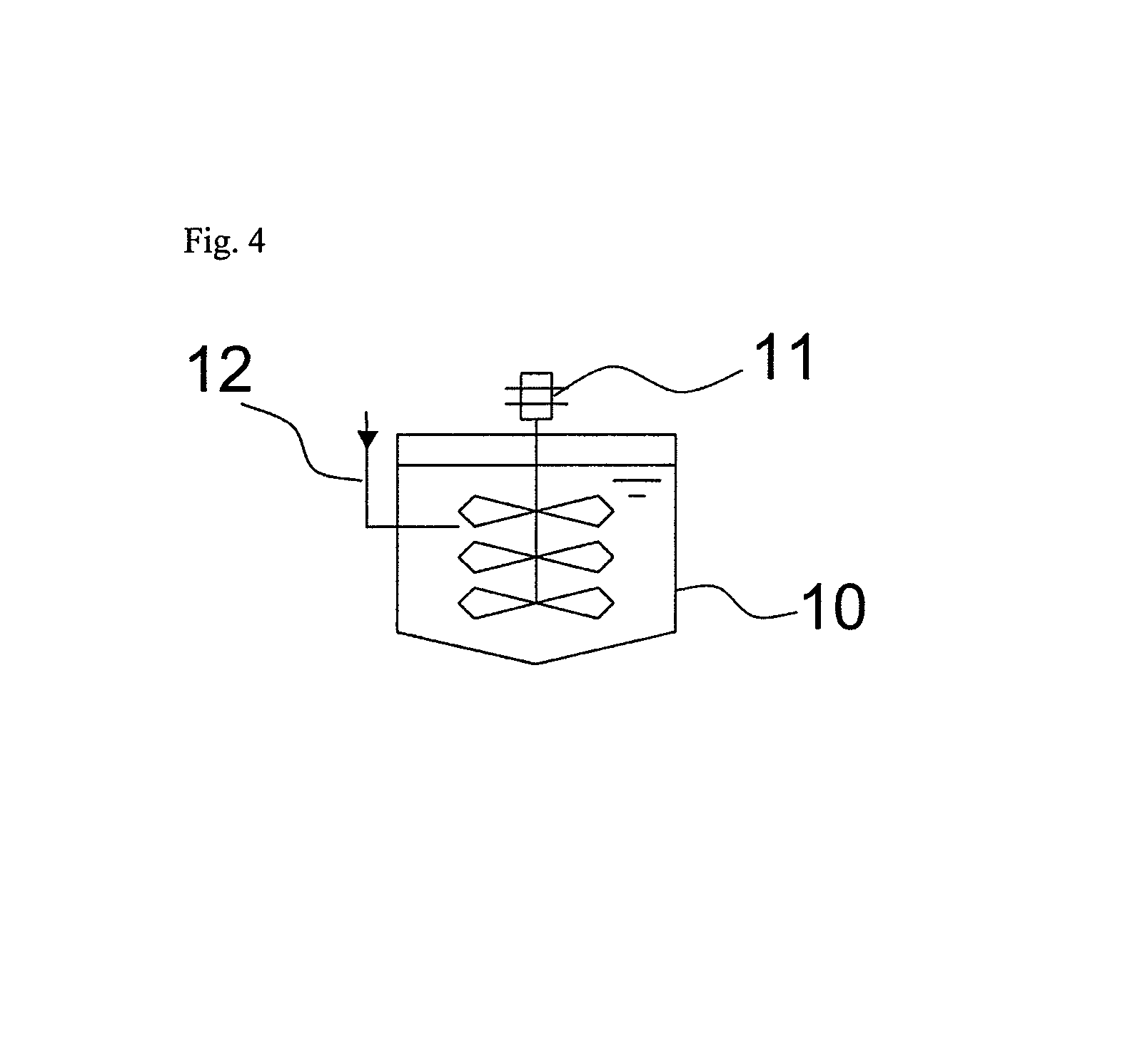
[0058]In a 1-L stirring vessel equipped with a jacket cooler (inner diameter of the vessel: 10.5 cm), an SUS pipe (inner diameter: 6 mm) was placed as an acrylonitrile feed tube which supplies acrylonitrile, such that the open end (feed opening) of the tube was positioned at a height of 3 cm from the bottom of the vessel. To this stirring vessel, 621 g of 50 mM phosphate buffer (pH 7.0) and 1.5 g of a bacterial cell suspension as a microbial catalyst were fed, and the liquid temperature was controlled to 21° C. by allowing cooling water at 5° C. to flow through the jacket. At this time, the position of the feed opening was 4 cm below the liquid level. The shortest distance between the feed opening and its closest paddle blade was 1 cm.

[0059]While the liquid temperature in the vessel was kept at 21° C., acrylonitrile with a purity of 99.7% was fed to the vessel via the acrylonitrile feed tube to start the reaction. During the reaction, the reaction liquid was mixed by stirring with a...

example 2

[0061]The reaction was carried out in the same manner as in Example 1 except that an additional SUS pipe having an inner diameter of 2 mm and a length of 2 cm was connected to the acrylonitrile feed tube such that the open end (feed opening) of this additional pipe was positioned at a height of 3 cm from the bottom of the vessel. The linear velocity of acrylonitrile at the feed opening was 0.04 m / s.

[0062]Eight hours after the beginning of the reaction, the reaction liquid was subjected to measurement by gas chromatography in the same manner as in Example 1, and, as a result, 10 ppm unreacted acrylonitrile was detected, and 50.4% acrylamide was detected. The yield of acrylamide from acrylonitrile was 99.7%. The conditions for supplying acrylonitrile and the reaction results are shown in Table 1.

example 3

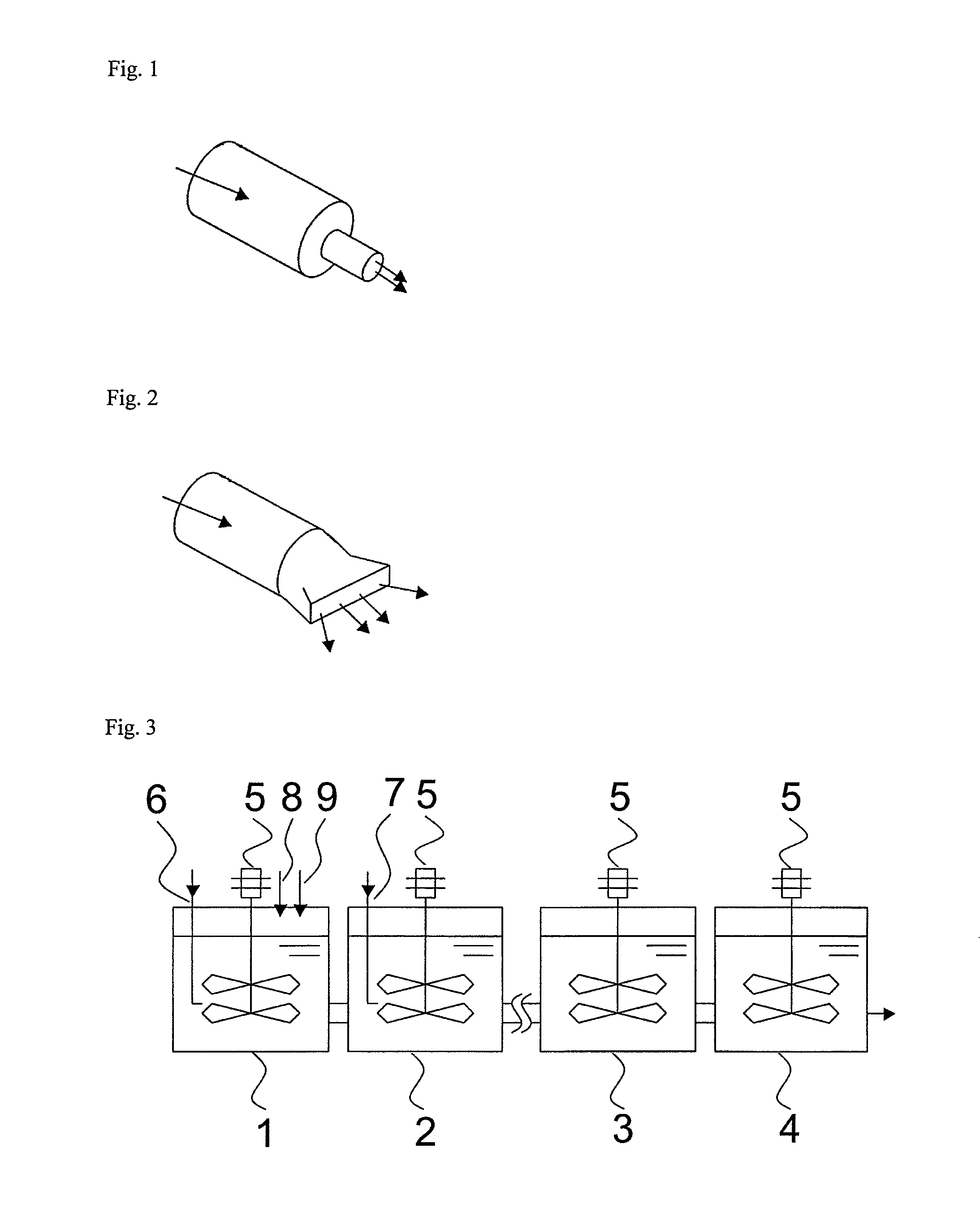
[0068]Six 1-L stirring vessels each equipped with a jacket cooler (inner diameter of the vessel, 10.5 cm; liquid depth, 11.5 cm) were connected in series. The first vessel was connected to the second vessel through a pipe communicating with the insides of these vessels at positions expected to be below the liquid levels during the reaction. Similarly, the second vessel and the third vessel, the third vessel and the fourth vessel, the fourth vessel and the fifth vessel, and the fifth vessel and the sixth vessel are connected to each other. In the sixth vessel, a pipe for discharging the liquid in the vessel was provided at the bottom of the vessel.

[0069]In each of the first, second and third vessels, an SUS pipe for feeding acrylonitrile (inner diameter, 6 mm) was provided as an acrylonitrile feed tube such that the open end (feed opening) of the tube was positioned at a height of 3 cm from the bottom of the vessel (8.5 cm below the liquid level).

[0070]Further, to the first vessel, a...


PUM

PropertyMeasurementUnit
linear velocityaaaaaaaaaa
speedaaaaaaaaaa
Froude numberaaaaaaaaaa

Abstract

A method for producing acrylamide from acrylonitrile by a biocatalyst method, wherein both evaporation of acrylonitrile into a gas phase and damaging of a catalyst by stirring are prevented, is provided. In the present invention, the production of acrylamide from acrylonitrile by the biocatalyst method comprises feeding acrylonitrile into an aqueous medium comprising a microbial catalyst.

Description

CROSS-REFERENCE TO RELATED APPLICATIONS[0001]This application is the U.S. National Phase under 35 U.S.C. §371 of International Application PCT / JP2010 / 073038, filed Dec. 21, 2010, which was published in a non-English language, which claims priority to JP 2009-294613, filed Dec. 25, 2009.TECHNICAL FIELD[0002]The present invention relates to a method for producing acrylamide from acrylonitrile by an action of nitrile hydratase derived from a microorganism.BACKGROUND ART[0003]Acrylamide is used as an industrially important substance in a wide range of areas. For example, acrylamide polymers are widely used as flocculants for wastewater treatment, paper strength agents, oil recovery agents and the like. Acrylamide has been conventionally industrially produced by hydrating the corresponding acrylonitrile using reduced copper as a catalyst. Recently, however, a method using a microbial catalyst instead of a copper catalyst (biocatalyst method) has been developed and partially practically ...

Claims


Application Information

Patent Timeline
Patent Type & Authority Patents(United States)
IPC IPC(8): C12P13/02C12M1/00
CPCC12M29/06C12P13/02
Inventor KARIYA, TAKAMITSUBANBA, HIROYASUKANO, MAKOTO
Owner MITSUBISHI CHEM CORP
Why Eureka
Try Eureka