Method for recovering a used slurry

a technology for polishing slurry and used slurry, which is applied in the direction of multi-stage water/sewage treatment, membranes, separation processes, etc., can solve the problems of additional treatment cost, and achieve the effect of improving contacting efficiency, facilitating processing, and improving contacting efficiency

Active Publication Date: 2012-06-19
NOMURA MICRO SCI CO LTD
View PDF29 Cites 8 Cited by
  • Summary
  • Abstract
  • Description
  • Claims
  • Application Information

AI Technical Summary

Benefits of technology

[0051]For example, a reverse osmosis membrane made of polyamide-based composite film and having a salt stopping ratio of 90% or more may be used. In this case, the additive components of the polishing slurry in the thus obtained concentrated liquid are concentrated and then, the polishing slurry can be recovered by transferring the concentrated liquid into the container with no re-addition of the additive components. As occasion demands, nitric acid may be added into the container such that the pH of the recovered polishing slurry can be finely controlled.
[0056]In order to enhance the contacting efficiency with the filtrate to be treated, a short fiber base as exemplified above may be effectively employed. In this case, the length of the short fiber may be preferably set within a range of 0.05 to 10 mm, more preferably within a range of 0.1 to 3 mm. The diameter of the short fiber may be preferably set within a range of 1 to 500 μm, more preferably within a range of 5 to 200 μm. The aspect ratio of the short fiber is preferably set within a range of 1.1 to 600, more preferably within a range of 1.5 to 100. A long fiber of a length of 5 mm or more may be combined with the short fiber.
[0057]The long fiber material can be easily processed in sheet form or felt form. On the other hand, the short fiber material has a higher contacting efficiency with the polishing slurry than the long fiber material. In this point of view, the short fiber material may be preferably used in the polishing step of wafer because the metallic ions under low concentration are intended to be removed. On the other hand, it is not required to remove the metallic ions under low concentration in the polishing step such as a CMP step for manufacturing devices. In this case, the concentration of the metallic ion in the polishing slurry becomes one hundred times as high as the one of the wafer polishing step so that the metallic ion burden for the chelate forming fibers is increased and thus, the chelate forming fibers must be exchanged frequently. In the polishing step such as the CMP step, therefore, the long fiber material may be preferably used because the long fiber material can be easily handled and processed.
[0065]According to the present invention, the used polishing slurry containing a washing water is concentrated so that metallic components are removed from the thus concentrated filtrate, and the concentration of the concentrated filtrate of the used polishing slurry is controlled to a predetermined concentration. Therefore, the effective components contained in the concentrated filtrate (used polishing slurry) can be reused and no slurry waste is required to be treated.

Problems solved by technology

In the latter case, it costs to conduct the additional treatment.

Method used


Image

  • Method for recovering a used slurry
  • Method for recovering a used slurry
  • Method for recovering a used slurry

Examples


example 1

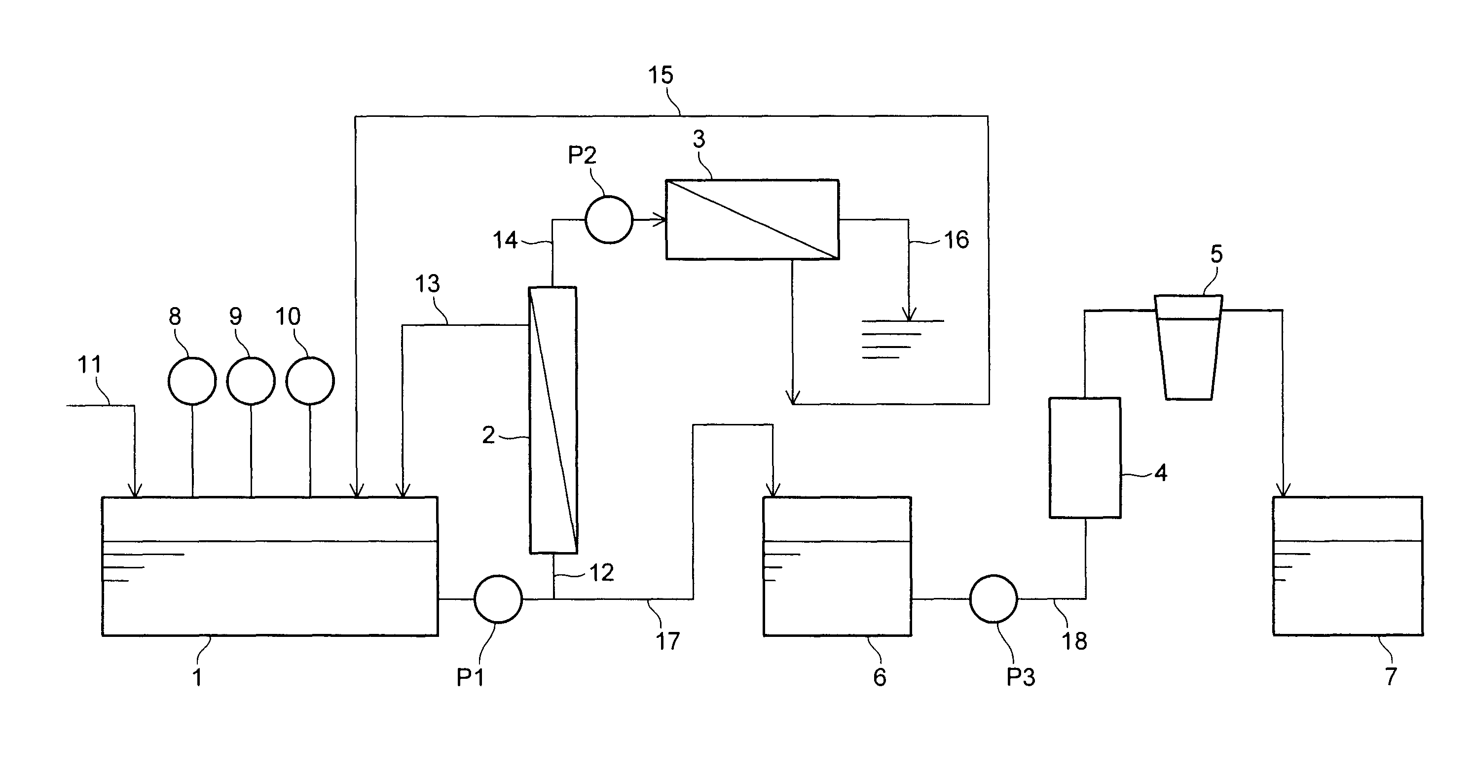
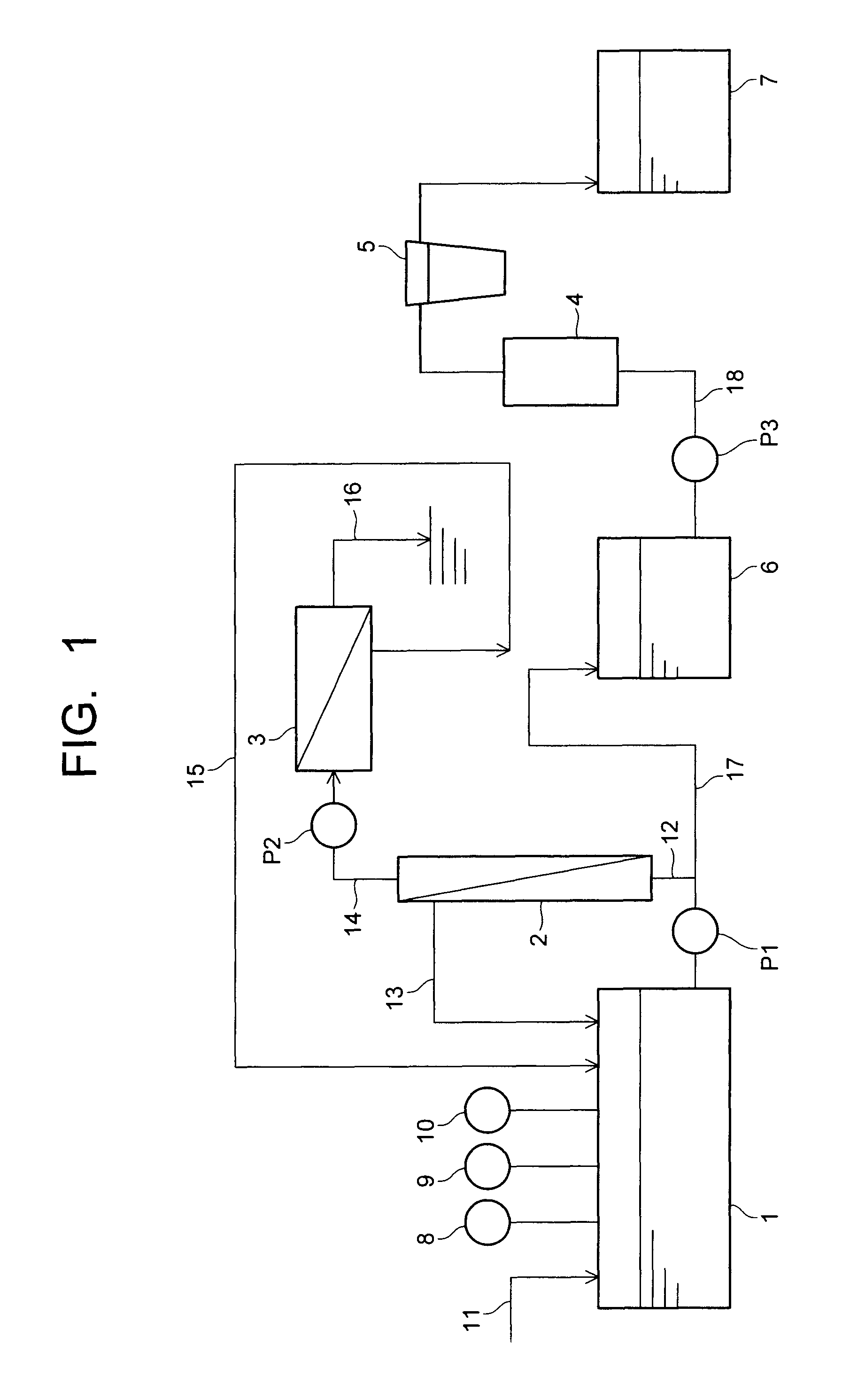
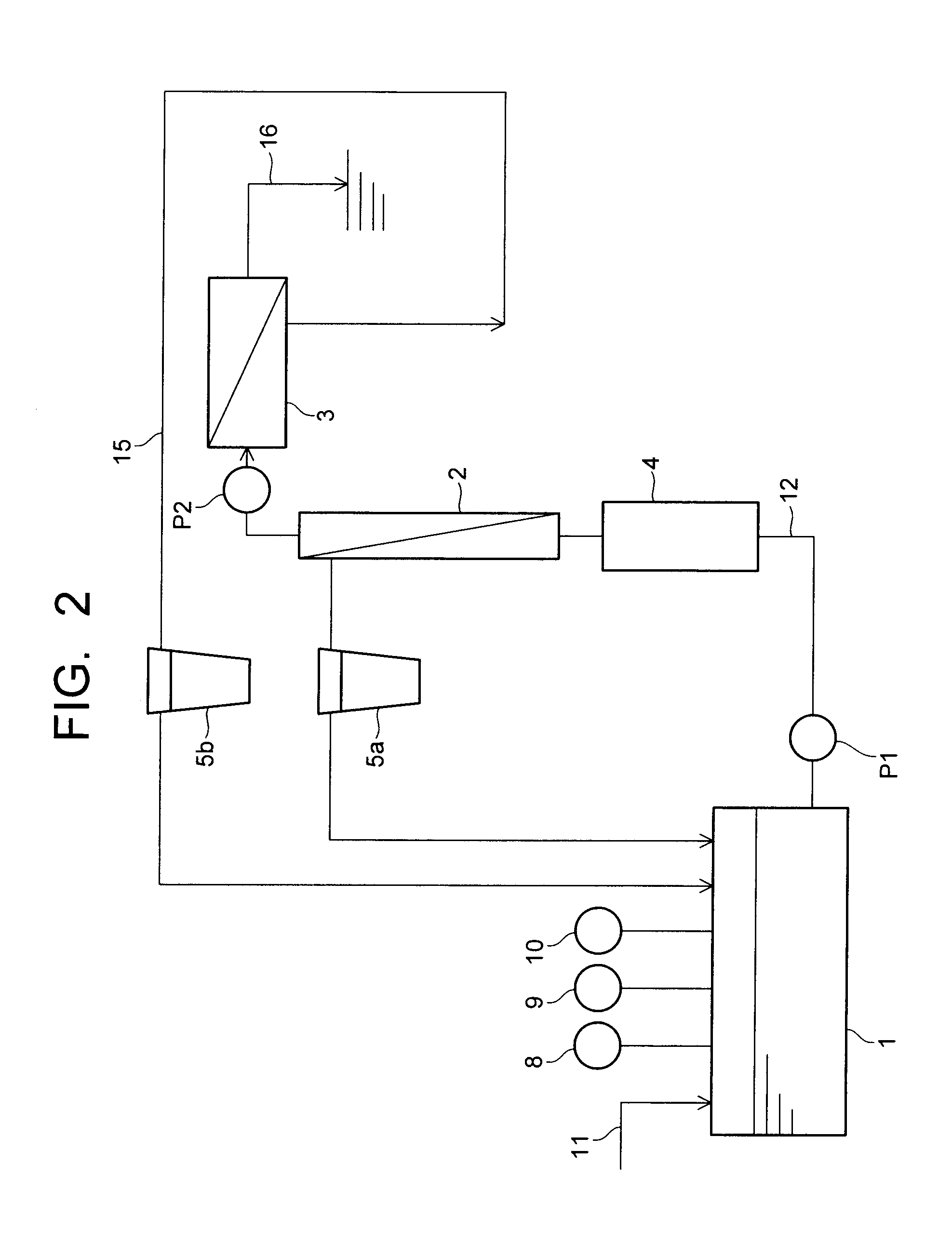
[0085]The slurry waste (used polishing slurry) of a polishing agent to be used in a planarization process was recovered as follows. First of all, a ceramic filter made of an Al2O3 base and a ZrO2 coating was prepared so that the water component and the silica abrasives of the polishing agent were separated with the ceramic filter. The pore diameter of the ceramic filter was set to 0.05 μm. The ceramic filter causes the increase of the abrasive density in the slurry waste. The circulating flow rate of the slurry waste for the ceramic filter was set to 4 m / sec so that about 35 L of the slurry waste can be filtered (treated) per one hour (namely, about 35 L of the filtrate can be obtained).

[0086]The thus obtained filtrate was transferred to a RO film (a polyamide film UTC-80 made by Toray Industries, Inc). In this case, the concentrating ratio (amount of supplied water / amount of concentrated water) was set to two.

[0087]The tungsten element and titanium element contained in the slurry w...

example 2

[0090]5 kg of chelate fiber (CG-50 (trade name)) was packed in a cylindrical container with a diameter of 150 mm and a length of 850 mm to form a chelate module. Then, the slurry waste was fed to the chelate module from the intermediate tank 6 at a rate of 0.3 L / min. The feeding rate of 0.3 L / min was determined in view of the selective removal of the iron element and the tungsten element contained in the slurry waste. The iron element was originated from an additive to the slurry waste and the tungsten element was originated from a substance to be polished. In this case, the tungsten element was removed while the iron element was left.

[0091]The results of the examples are listed in Table 1. The sample was named as follows. The sample obtained from the piping 11 was named as a “slurry waste”, and the sample obtained from the piping 13 corresponding to the concentration line of the ceramic filter 2 was named as a “concentrated solution (1)”. The sample obtained from the piping 15 corr...


PUM

PropertyMeasurementUnit
median sizeaaaaaaaaaa
pore diameteraaaaaaaaaa

Abstract

Foreign substances which are not inherently contained in a polishing slurry are selectively separated and removed from a polishing slurry component comprised of abrasives, a solvent and an additive which are inherently contained in the polishing slurry.

Description

CROSS-REFERENCE TO RELATED APPLICATIONS[0001]This application is based upon and claims the benefit of priorities from the prior Japanese Patent Application No. 2008-335317 filed on Dec. 26, 2008 and Japanese Patent Application No. 2009-147163 filed on Jun. 22, 2009; the entire contents which are incorporated herein by reference.BACKGROUND[0002]1. Field of the Invention[0003]The present invention relates to a method for recovering a semiconductor polishing slurry (hereinafter, often called as “polishing slurry”) which would be used in a polishing step in a manufacturing process of semiconductor, and particularly to a method for recovering a used semiconductor polishing slurry with active elements such as abrasives and (an) additive(s) which are dissolved in the dispersion medium of the used slurry, whereby the abrasives and the additive(s) can be recovered with no additional addition of the abrasives, the additive agent(s) for repeating the polishing step.[0004]The manufacturing proc...

Claims


Application Information

Patent Timeline
Patent Type & Authority Patents(United States)
IPC IPC(8): B01D61/00B08B7/04C02F9/00B24B57/02H01L21/304
CPCB01D61/025B01D61/04B01D2311/04B01D2311/08B01D2311/12B01D2311/2649B01D2311/2623
Inventor ABE, MITSUGUIIYAMA, MASAMITSU
Owner NOMURA MICRO SCI CO LTD
Why Eureka
Try Eureka