Polarizing plate and liquid crystal display comprising the same

a technology of liquid crystal display and polarizing plate, which is applied in the direction of polarizing elements, instruments, optics, etc., can solve the problems of complicated process, color quality, contrast ratio and/or viewing angle reduction, and the modification of liquid crystal panel has limitations in improving color quality and contrast ratio,

Active Publication Date: 2016-09-01
SAMSUNG SDI CO LTD
View PDF8 Cites 60 Cited by
  • Summary
  • Abstract
  • Description
  • Claims
  • Application Information

AI Technical Summary

Benefits of technology

[0006]According to an example embodiment of the present invention, a polarizing plate includes: a polarizer; a pattern layer on one surface of the polarizer, the pattern layer including a first refractive index layer having at least one engraved pattern and a second refractive index layer having a filling pattern filling at least a portion of the engraved pattern, the first refractive index layer having a higher refractive index than the second refractive index layer; and a first protective layer. The polarizing plate has a stack structure in which the polarizer, the second refractive index layer, the first refractive index layer and the first protective layer are sequentially stacked in that order, or a stack structure in which the polarizer, the first protective layer, the second refractive index layer and the first refractive index layer are sequentially stacked in that order. The first protective layer includes a base film including at least one resin of triacetylcellulose, polyethylene terephthalate, cyclic olefin polymer, and acrylic resins.

Problems solved by technology

However, the liquid crystal display generally exhibits lower qualities at lateral sides thereof in terms of color quality, contrast ratio and / or viewing angle in comparison to the front side thereof.
However, modification of the liquid crystal panel has limitations in improvement of color quality and contrast ratio at the lateral sides of the liquid crystal display and generally requires a complicated process.
Moreover, the liquid crystal display undergoes increasing deterioration in brightness uniformity with increasing screen size of the liquid crystal display.
Accordingly, a separate liquid crystal display module is generally provided depending upon screen size, thereby deteriorating processability and economic feasibility

Method used


Image

  • Polarizing plate and liquid crystal display comprising the same
  • Polarizing plate and liquid crystal display comprising the same
  • Polarizing plate and liquid crystal display comprising the same

Examples


example 4

Manufacture of Polarizing Plate

[0107]A polarizer was manufactured in substantially the same manner as in Example 1.

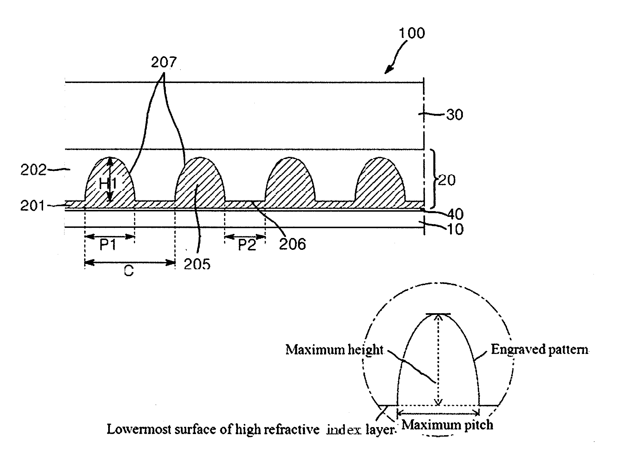
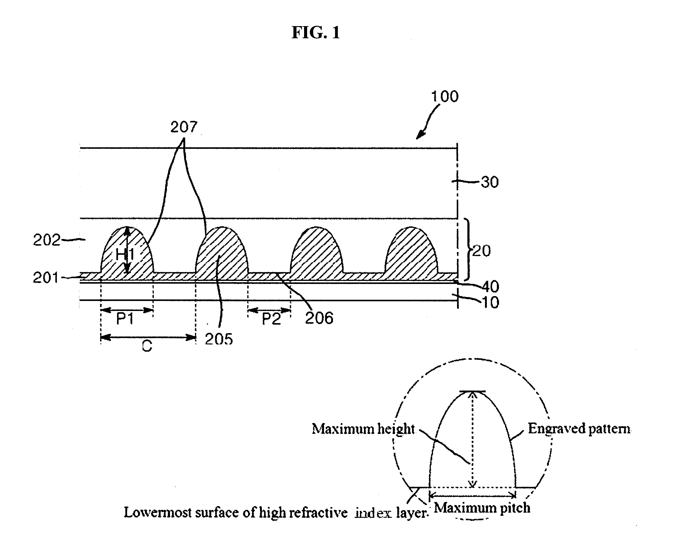
[0108]A coating layer was formed by coating a UV-curable resin (SSC155, Shin-A T&C) onto one surface of a transparent PET film (COSMOSHINE SRF, thickness: 80 μm, Re=14,000 nm at a wavelength of 550 nm, Toyobo Co., Ltd.) for a first protective layer. Using a film having an embossed prism pattern (pitch: 13 μm, height: 10 μm, vertex angle: 65.5°, triangular cross-section) formed thereon, an engraved prism pattern was formed on the coating layer, followed by curing, thereby forming a high refractive index layer on the PET film. Then, a UV-curable resin (SSC143, Shin-A T&C) was coated onto the high refractive index layer such that the engraved prism pattern could be completely filled with the UV-curable resin, followed by curing, thereby forming a pattern layer having a low refractive index layer directly formed on the high refractive index layer.

[0109]A bonding agent for p...

example 5

Manufacture of Polarizing Plate

[0110]A polarizer was manufactured in substantially the same manner as in Example 1.

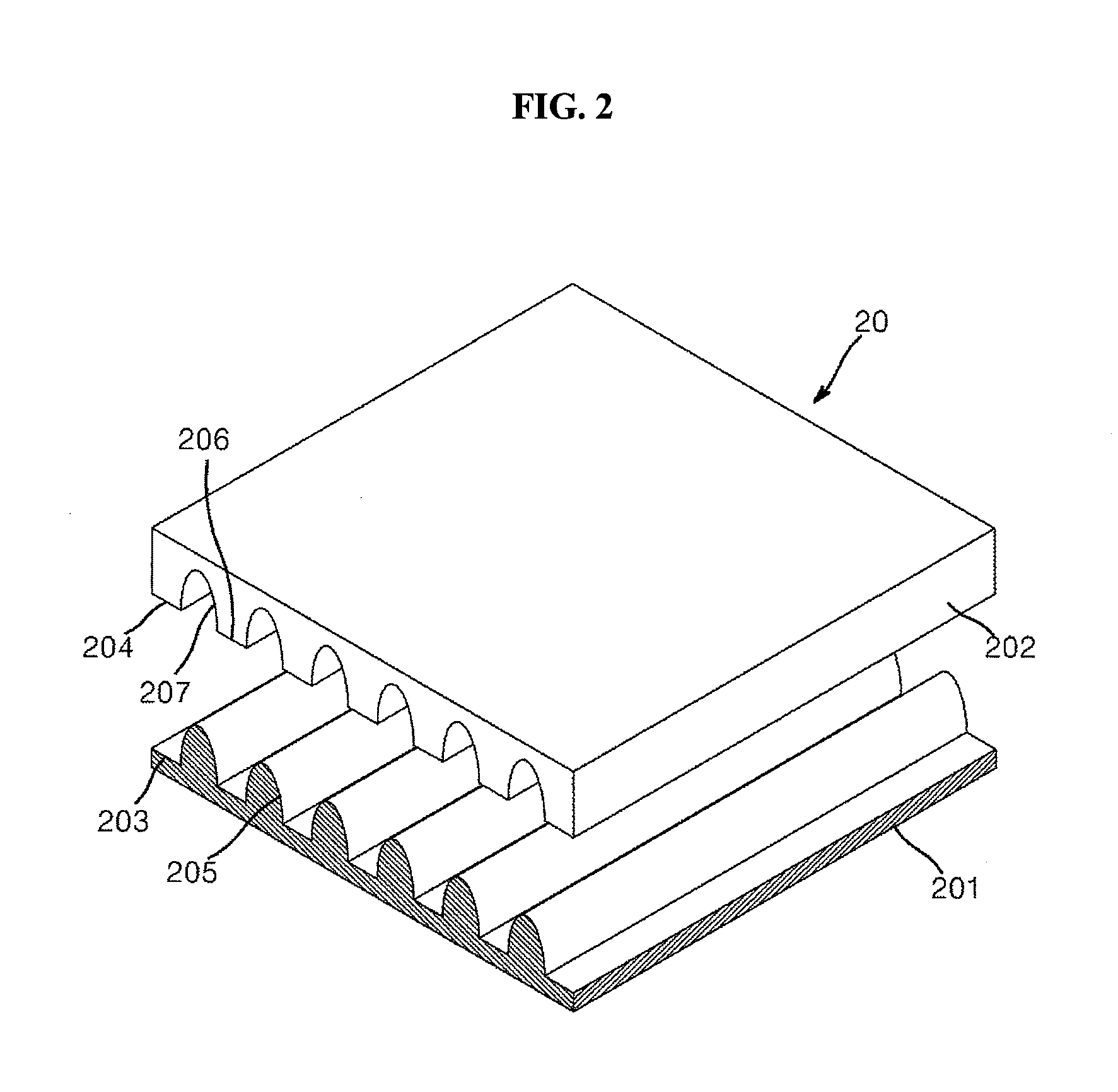
[0111]A coating layer was formed by coating a UV-curable resin (SSC155, Shin-A T&C) onto one surface of a transparent PET film (COSMOSHINE SRF, thickness: 80 μm, Re=14,000 nm at a wavelength of 550 nm, Toyobo Co., Ltd.) for a first protective layer. Using a film having an embossed lenticular lens pattern (pitch: 10 μm, height: 10 μm) and a flat portion (pitch: 10 μm) alternately formed thereon, an engraved lenticular lens pattern and a flat portion were formed on the coating layer, followed by curing, thereby forming a high refractive index layer on the PET film. Then, a UV-curable resin (SSC143, Shin-A T&C) was coated onto the high refractive index layer such that the engraved lenticular lens pattern could be completely filled with the UV-curable resin, followed by curing, thereby forming a pattern layer having a low refractive index layer directly formed on the high r...

example 6

Manufacture of Polarizing Plate

[0113]A polarizer was manufactured in substantially the same manner as in Example 1.

[0114]A coating layer was formed by coating a UV-curable resin (SSC155, Shin-A T&C) onto one surface of a transparent TAC film (KC4DR-1, thickness: 40 μm, Konica Co., Ltd.) for a first protective layer. Using a film having an embossed lenticular lens pattern (pitch: 10 μm, height: 10 μm) and a flat portion (pitch: 10 μm) alternately formed thereon, an engraved lenticular lens pattern and a flat portion were formed on the coating layer, followed by curing, thereby forming a high refractive index layer on the TAC film. Then, a UV-curable resin (SSC143, Shin-A T&C) was coated onto the high refractive index layer such that the engraved lenticular lens pattern could be completely filled with the UV-curable resin, followed by curing, thereby forming a pattern layer having a low refractive index layer directly formed on the high refractive index layer.

[0115]A bonding agent for...


PUM

PropertyMeasurementUnit
refractive indexaaaaaaaaaa
light transmittanceaaaaaaaaaa

Abstract

A polarizing plate includes: a polarizer; a pattern layer on one surface of the polarizer, the pattern layer including a first refractive index layer having at least one engraved pattern and a second refractive index layer having a filling pattern filling at least a portion of the engraved pattern, the first refractive index layer having a higher refractive index than the second refractive index layer; and a first protective layer. The polarizing plate has a structure in which the polarizer, the second refractive index layer, the first refractive index layer and the first protective layer are sequentially stacked in that order, or in which the polarizer, the first protective layer, the second refractive index layer and the first refractive index layer are sequentially stacked in that order. The first protective layer includes a base film including at least one resin of triacetylcellulose, polyethylene terephthalate, cyclic olefin polymer, and acrylic resins.

Description

CROSS-REFERENCE TO RELATED APPLICATIONS[0001]This application claims priority to and the benefit of Korean Patent Application No. 10-2015-0028637, filed on Feb. 27, 2015 and Korean Patent Application No. 10-2015-0156117, filed on Nov. 6, 2015 in the Korean Intellectual Property Office, the entire disclosures of both of which are incorporated herein by reference.FIELD[0002]Embodiments of the present invention relate to a polarizing plate and a liquid crystal display including the same.DESCRIPTION OF THE RELATED ART[0003]A liquid crystal display includes a liquid crystal panel that receives light from a backlight unit, and selectively transmits the light during operation. This way, the liquid crystal display typically provides good color quality at a front side thereof. However, the liquid crystal display generally exhibits lower qualities at lateral sides thereof in terms of color quality, contrast ratio and / or viewing angle in comparison to the front side thereof.[0004]The liquid cr...

Claims


Application Information

Patent Timeline
Patent Type & Authority Applications(United States)
IPC IPC(8): G02B5/30G02B1/14G02F1/1335
CPCG02B5/305G02B5/3083G02B1/14G02F1/133528G02F1/133507C09K2323/03C09K2323/035
Inventor LEE, SEONG HOONOH, YOUNGLEE, JEONG HOJU, YOUNG HYUN
Owner SAMSUNG SDI CO LTD
Why Eureka
Try Eureka