Flexible display panel

a flexible display panel and display panel technology, applied in the field of display panels, can solve the problems of easy easy breakage of the fanout area, and damage to the display area when bending, so as to reduce the damage to the display area upon bending the flexible display panel, the effect of avoiding or reducing the damage to the screen upon bending

Active Publication Date: 2016-09-01
BOE TECH GRP CO LTD
View PDF5 Cites 10 Cited by
  • Summary
  • Abstract
  • Description
  • Claims
  • Application Information

AI Technical Summary

Benefits of technology

[0023](1) by utilizing a zig-zag wiring manner in the fanout area between the driver IC and the display area, or between the gate driver on array circuit and the display area, damage to the fanout wires such as metal wires upon bending is reduced, bending resistance of the fanout area is improved and damage to the screen upon bending the flexible display panel is avoided or reduced.
[0024](2) by utilizing a zig-zag wiring manner in the fanout area between the driver IC and the display area, or between the gate driver on array circuit and the display area, the length and the width of the fanout area are efficiently reduced and thus it is advantageous for the flexible display panel to achieve a multi-directional bending.
[0025](3) by disposing the driver IC or the gate driver on array circuit at four corners of the display area, the driver IC or the gate driver on array circuit will not be damaged when the flexible display panel is bent and an all-direction undamaged bending of the flexible display panel is realized.

Problems solved by technology

The screen is easy to be damaged when the flexible display panel is bent.
The damage is not only present in a display area (active area) of the flexible display panel, but also present in a fanout area between the display area and a driver circuit area.
With this wiring manner, the bending force generated when bending the flexible display panel totally acts on the linear wires of the fanout area 2, as a result, the fanout area 2 is easy to be broken and damaged when bending.
Though the gate driver on array circuit is bendable in this case, it is easy to be damaged and the characteristics thereof may change during the bending.

Method used


Image

  • Flexible display panel
  • Flexible display panel
  • Flexible display panel

Examples


Embodiment Construction

[0033]In order to make objects, technical solutions and advantages of the invention more clear and apparent, hereinafter, the technical solutions of the invention will be described in detail in connection with the specific embodiments and referring to the accompanying drawings.

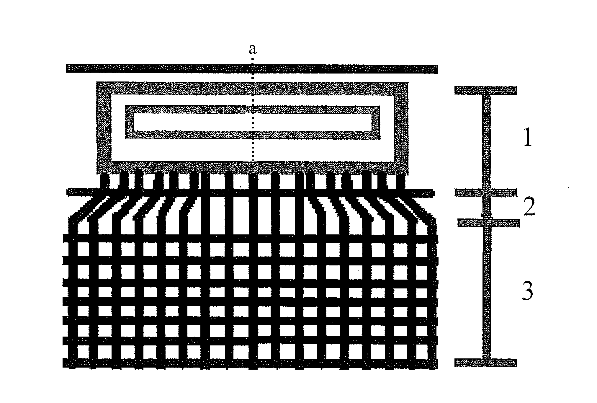
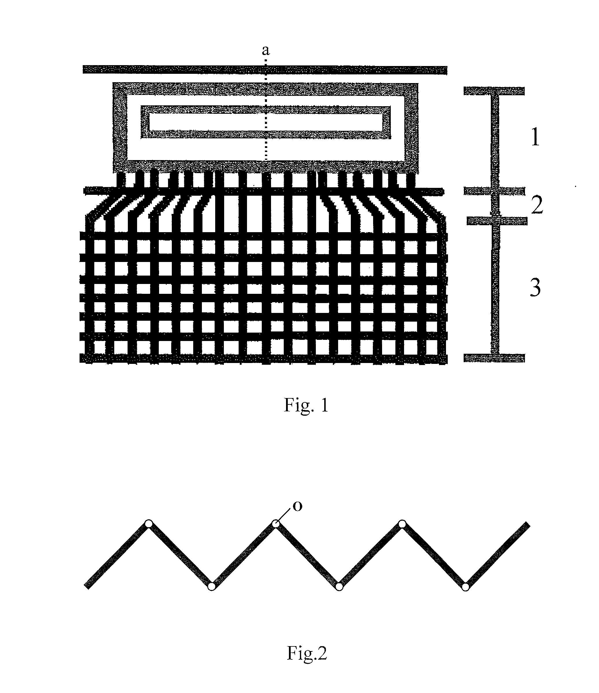
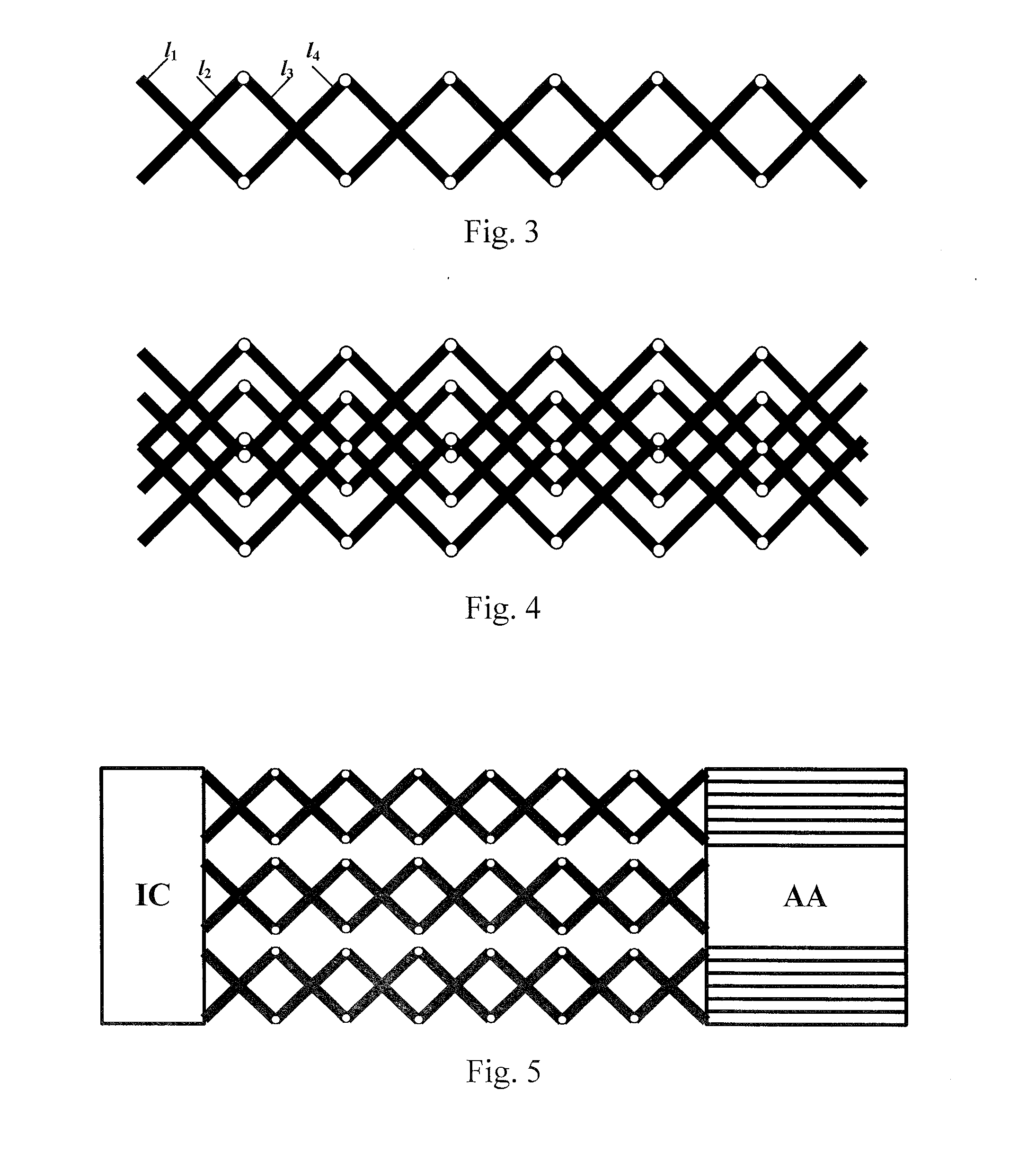
[0034]The essential concept of the flexible display panel according to the embodiments of the present invention is: by utilizing a zig-zag wiring manner in the fanout area between the display area (AA) and the driver circuit area, damage to metal wires upon bending is reduced, bending resistance of the fanout area is improved and damage to the screen when bending the flexible display panel is avoided or reduced, thereby realizing an undamaged bending of the flexible display panel.

[0035]According to an embodiment of the present invention, the flexible display panel comprises at least an display area, a fanout area and a driver circuit area. The fanout area is positioned between the display area and the driver c...


PUM


Abstract

Embodiments of the present invention disclose a flexible display panel. The flexible display panel at least comprises an display area, a fanout area and a driver circuit area, wherein the fanout area is positioned between the display area and the driver circuit area to connect the display area with the driver circuit area, and the fanout area comprises at least one zig-zag fanout wire, each of which comprises a plurality of fanout wire segments divided by bending points. In the technical solutions of the present invention, by utilizing a zig-zag wiring manner, damage to metal wires when bending is reduced, bending resistance of the fanout area is improved and damage to the screen when bending the flexible display panel is avoided or reduced.

Description

CROSS-REFERENCE TO RELATED APPLICATION[0001]This application claims the benefit of Chinese Patent Application No. 201410383884.3 filed on Aug. 6, 2014 in the State Intellectual Property Office of China, the whole disclosure of which is incorporated herein by reference.BACKGROUND OF THE INVENTION[0002]1. Field of the Invention[0003]Embodiments of the present invention relate to a technical field of display panel, in particular, to a flexible display panel and a display apparatus comprising the display panel.[0004]2. Description of the Related Art[0005]The flexible display panel is a bendable and deformable display panel or display screen made of flexible material, and it has many advantages such as low power consumption, small size, lightweight, easy to install, convenient for transportation, diverse display manners, excellent display quality and so on. The flexible display panel is mainly used in portable electronic devices and touch input device, etc., and it has a broad developing...

Claims


Application Information

Patent Timeline
Patent Type & Authority Applications(United States)
IPC IPC(8): H01L27/12
CPCH01L27/1218H01L27/1244H01L23/48H01L2924/0002G09G2380/02G02F1/133305G02F1/13452H01L2924/14H10K59/179H10K59/131H10K77/111H01L2924/00H01L23/52H01L23/5387H01L23/5386H01L23/538
Inventor SONG, SONGKAZUYOSHI, NAGAYAMA
Owner BOE TECH GRP CO LTD
Why Eureka
Try Eureka