Perspiration sensor

a technology of perspiration sensor and sensor body, which is applied in the field of moisture sensor, can solve the problems of not providing quantitative indication of the volume or level of perspiration, and achieve the effects of facilitating moisture absorption, minimizing the introduction of noise, and reducing environmental nois

Active Publication Date: 2016-09-08
MEDIDATA SOLUTIONS
View PDF2 Cites 40 Cited by
  • Summary
  • Abstract
  • Description
  • Claims
  • Application Information

AI Technical Summary

Benefits of technology

[0009]In accordance with the invention, the perspiration sensor can be constructed having three layers, a first or top layer, a second or middle layer and a third or bottom layer. The bottom layer can include an adhesive or other skin contacting material that maintains contact with and capacitively couples the sensor to the skin. The bottom layer and the top layer include the first and second electrode plates that form the capacitor with dielectric material surrounded by the middle layer sandwiched in between. The bottom layer, middle layer and top layer form a central chamber that encloses the dielectric material and positions it in a dielectric space between the first and second electrodes. The bottom layer can also include one or more pores, inlets or vents that enable perspiration released from the skin to enter central chamber and be absorbed by the dielectric material in the dielectric space. The bottom layer can also include a skin coupling electrode that becomes electrically coupled to the skin when the bottom surface of the bottom layer is adhered to or placed in contact with the skin. The skin coupling electrode can be electrically connected to the central chamber and the dielectric material. When the bottom surface includes an adhesive material, the skin coupling electrode capacitively couples the dielectric material in the central chamber to the skin to provide ground shielding adjacent to the electrodes to minimize environmental noise. In accordance with some embodiments of the invention, the dielectric material can be weakly but consistently (capacitively) coupled to earth ground through the skin.
[0010]Each of the layers can be formed from a rigid printed circuit board (PCB) or a flexible PCB, and each of the layers can be laminated together as is well known in the art. The dielectric material can be an absorbent material that rapidly replaces air with perspiration, such as a tufted microfiber cloth. The thickness of the middle layer can be selected to define and control the distance between the sensing electrode plates of the capacitor. In accordance with some embodiments, the middle layer includes a rigid material having a predefined thickness to tightly control the electrode plate spacing and slightly thinner than the thickness of the microfiber cloth causing portions of the cloth to extrude through the pores or inlets of the bottom layer facilitate moisture absorption.
[0011]In accordance with some embodiments of the invention, the device can further include a capacitance measurement integrated circuit (e.g., IC chip) mounted to the top layer that enables close proximity measurement of the change in capacitance of the sensor to minimize the introduction of noise. In this configuration, the measured capacitance can be transmitted (e.g., by wire or wirelessly) to a remote system for storing and / or analyzing the capacitance data and determining perspiration rates (e.g., volume and volume over time).
[0012]In accordance with some embodiments of the invention, the device can be fully or partially enclosed or encapsulated in polymer or elastomeric material (e.g. PDMS, or silicone) that protects the sensor from the environment. One or more of the layers can include one or more partially or fully enclosed anchor rings projecting from the perimeter of the device such that the polymer material passes through the opening in the anchor rings to more securely anchor the encapsulating material to the outside of the device.
[0013]In operation, the bottom of the device is coupled to the skin by an adhesive material and perspiration released by the skin passes through the inlets and become absorbed by the microfiber dielectric material. The capacitance of the first and second electrodes changes as the dielectric material absorbs perspiration. In addition, the bottom of the device includes a skin electrode that is electrically connected to the dielectric material and the central chamber. The skin electrode can be electrically connected to the middle layer by plated through holes or vias in the bottom layer. The vias in the middle layer can include electrodes that directly contact the dielectric material, enabling the dielectric material to be coupled (e.g., capacitively coupled) to the skin through the adhesive. The integrated circuit on the top layer includes a circuit that determines a measure of the capacitance between the first and second electrodes while the skin electrode serves to stabilize the capacitance measurement against noise.

Problems solved by technology

These devices involve the measurement of the electrical resistance of the skin, but do not provide a quantitative indication of the volume or level of perspiration over time.

Method used


Image

  • Perspiration sensor
  • Perspiration sensor
  • Perspiration sensor

Examples


Embodiment Construction

[0028]The present invention is directed to methods and systems for obtaining a quantitative measurement of moisture. One specific application for the invention includes the detection and measurement of perspiration. For purposes of illustration, the invention is described herein in the context of measuring perspiration, however, embodiments of the invention can be used to measure other sources of moisture.

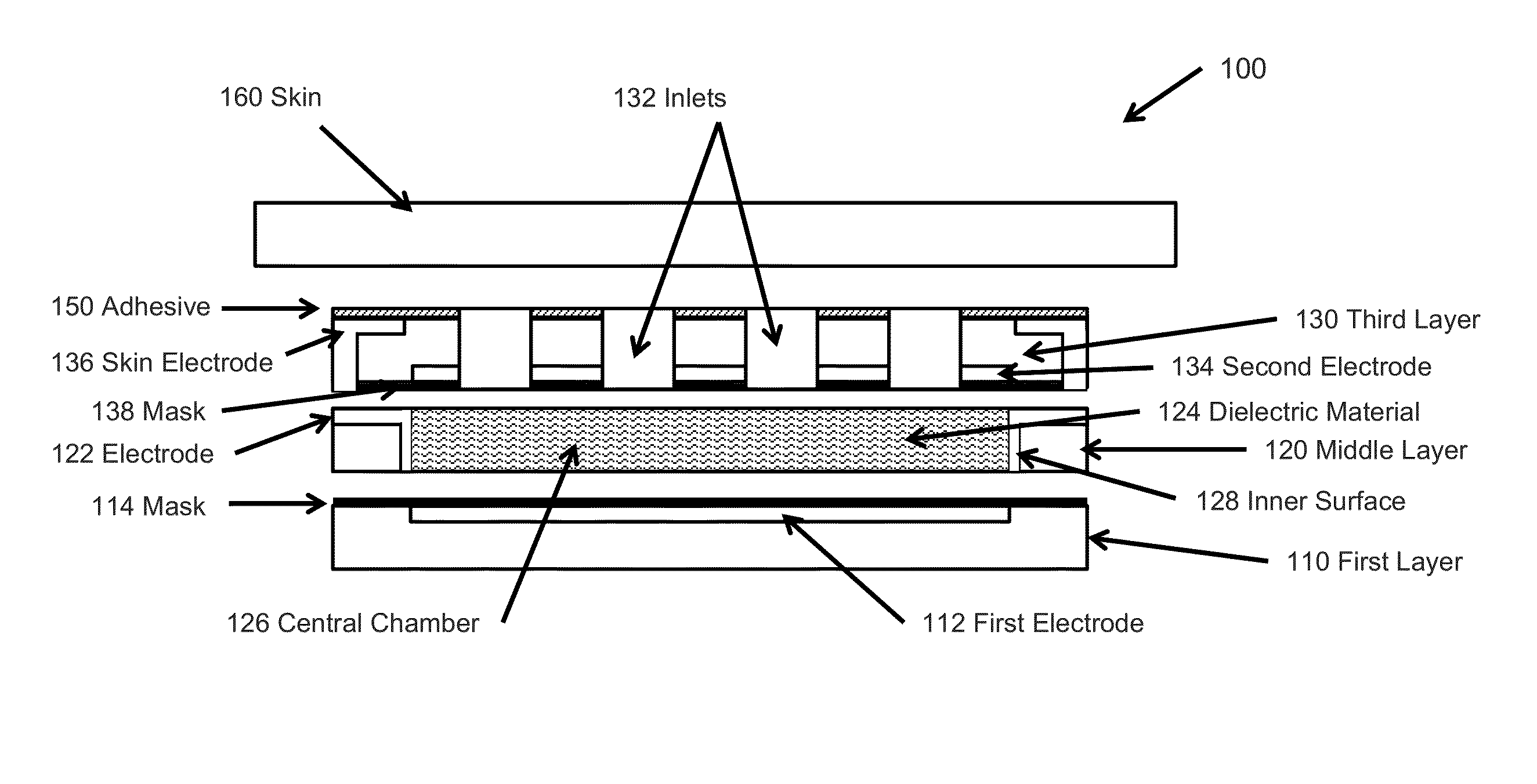
[0029]In accordance with some embodiments of the invention, the perspiration sensor includes a pair of ground shielded parallel electrodes sandwiching a moisture absorbent dielectric material (e.g., a microfiber cloth) that forms a capacitor. The sensor allows perspiration to become absorbed by moisture absorbent dielectric material which changes the dielectric constant the dielectric material and is reflected in the measured capacitance of the electrode plates of the perspiration sensor. In accordance with some embodiments of the invention, the dielectric material can be electrica...


PUM


Abstract

A moisture sensor includes a pair of electrode plates separated by a moisture absorbent material that forms the dielectric of a capacitive sensor. As the absorbent dielectric material absorbs moisture, such as perspiration, the capacitance of the sensor changes reflecting a quantitative measure of perspiration absorbed. The sensor can be stabilized by capacitively coupling the dielectric material to the skin of the user to improve sensor stability and noise rejection. The sensor can include a capacitive sensing integrated circuit that measures the capacitance of the sensor in close proximity to the electrodes to limit the introduction of noise.

Description

CROSS-REFERENCE TO RELATED APPLICATIONS[0001]This application claims any and all benefits as provided by law including benefit under 35 U.S.C. §119(e) of the U.S. Provisional Application No. 62 / 127124, filed Mar. 2, 1015, the contents of which are incorporated herein by reference in its entirety.STATEMENT REGARDING FEDERALLY SPONSORED RESEARCH[0002]Not ApplicableREFERENCE TO MICROFICHE APPENDIX[0003]Not ApplicableBACKGROUND[0004]1. Technical Field of the Invention[0005]The present invention is directed to a moisture sensor and more specifically, to a perspiration sensor for quantitatively measuring levels of perspiration. In accordance with some embodiments, the perspiration sensor includes a capacitive sensor that can be coupled to the skin and utilize capacitance to measure perspiration. The perspiration sensor can be shielded and stabilized to reduce noise by electrically coupling the capacitor dielectric material to the skin.[0006]2. Description of the Prior Art[0007]The prior a...

Claims


Application Information

Patent Timeline
Patent Type & Authority Applications(United States)
IPC IPC(8): A61B5/053A61B5/00
CPCA61B5/0537A61B5/14517A61B5/443A61B5/6832
Inventor MURPHY, BRIANHANSON, VALERIE SUSANSUN, HOI-CHEONG STEVEWEI, PING-HUNGPAPAKYRIKOS, COLEARANYOSI, ALEXANDER J.HONG, JI HYUNG
Owner MEDIDATA SOLUTIONS
Why Eureka
Try Eureka