
Method and Digital Tool for Engineering Software Architectures of Complex Cyber-Physical Systems of Different Technical Domains

a software architecture and technology of cyberphysical systems, applied in digital transmission, data switching networks, instruments, etc., can solve the problems of difficult generalization, affecting the validity of the relations of entities in another view, and not offering support for automatic tracing or checking of multi-view constraints, etc., to achieve efficient implementation, quick focus, and efficient

Active Publication Date: 2016-09-08
SIEMENS AG
View PDF31 Cites 17 Cited by
  • Summary
  • Abstract
  • Description
  • Claims
  • Application Information

AI Technical Summary

Benefits of technology

The proposed method and tool offer a way to efficiently and interactively engineer complex cyber-physical systems. It allows for dynamic visualizations, faster design space exploration, faster re-certification, and support for large systems. The tool combines graph-based modeling, a graph database, flexible constraint modeling, and rapid feedback to improve the process of engineering these systems.

Problems solved by technology

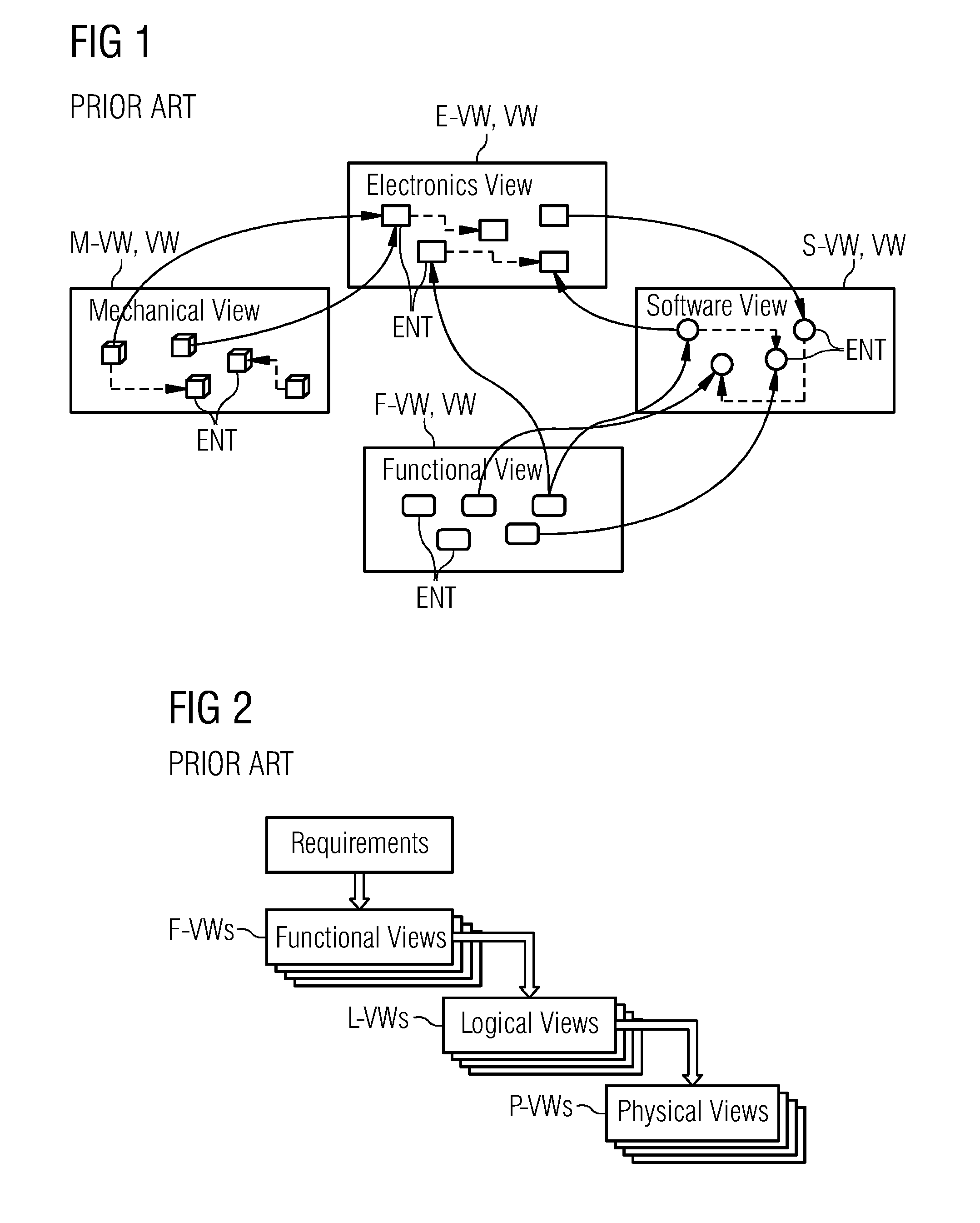
This implies, however, that the Constraints placed on the Entities in one View may affect the validity of the relations of the Entities in another View.
It is a challenging task to make sure that these multi-view Constraints are never invalidated in the process of system engineering.
AADL was first developed in the field of avionics (aerospace engineering) and was known formerly as the Avionics Architecture Description Language (cf. http: / / en.wikipedia.org / wiki / AADL in the version of Jun. 12, 2014), but are difficult to generalize, as well as don't offer support for automatic tracing or checking of multi-view Constraints.
There are no tools that provide rapid visual feedback across architectural Views.
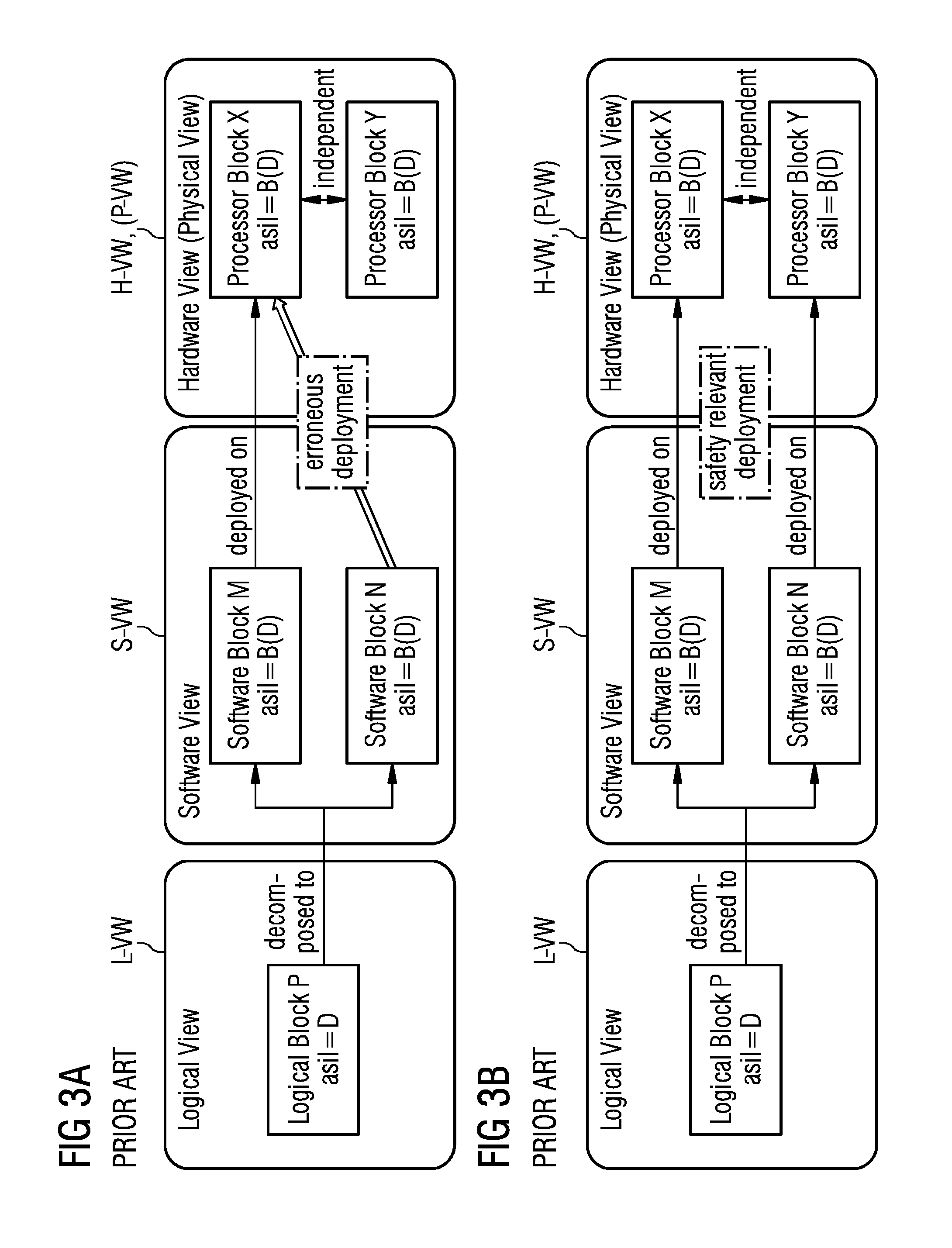
Yet, due to insufficient tool support for analyzing the architecture of a complex cyber-physical system, a majority of the safety analysis is done manually with office software like Excel and Word.
This situation results in very conservative design practices, as previously established architectures require less re-analysis.
Design-space exploration (e.g. evaluating the realization of a requirement in hardware vs. software) becomes very tedious.
Optimization synergies are also not fully exploited due to the same reason.
Safety certification is an expensive part of system development, the cost of which depends on efficient safety analysis.
However they are not economically feasible without some way of decreasing re-certification expenses.

Method used


Image

  • Method and Digital Tool for Engineering Software Architectures of Complex Cyber-Physical Systems of Different Technical Domains
  • Method and Digital Tool for Engineering Software Architectures of Complex Cyber-Physical Systems of Different Technical Domains
  • Method and Digital Tool for Engineering Software Architectures of Complex Cyber-Physical Systems of Different Technical Domains

Examples


Embodiment Construction

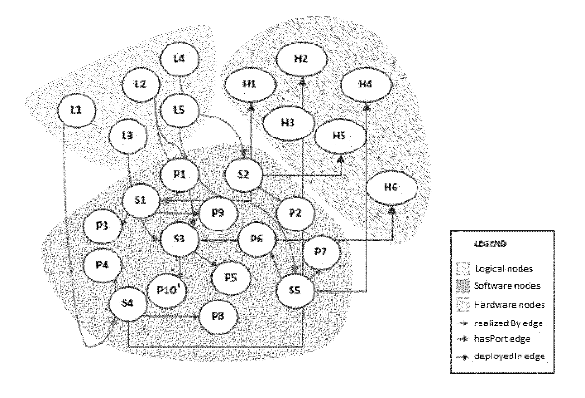
[0054]FIG. 4 depicts in a principle chart a Digital Tool DT that is interfaced to a user and two External Tools ET, from which may be used a first External Tool ET1 for Bulk Export / Import and a second External Tool ET2 for Interactive Export-Import. The Digital Tool DT may be designed as an “Application Software (APP)” including several “Software Components” and therein embedded various program modules henceforth referred to as “Modules”. The “Application Software” is thereby configured for running on at least one of a computer and a server, whereby the computer may be a desktop PC or “All-in-One” PC, a smart phone, a notebook, a tablet etc. Furthermore the “Application Software” may be stored on a storage media being insertable into the computer or the server or being part of the computer respectively the server. Moreover, the “Application Software” may be down- or uploaded into the computer, respectively the server, or with respect to cloud computing stored on at least one server....


PUM


Abstract

In order to engineer software architectures of complex cyber-physical systems of different technical domains such that both time and effort efficient and truly interactive engineering of software architectures of complex cyber-physical systems is enabled, it is proposed to provide an automatic enforcement of multi-level Constraints across architectural Views. This provides, (i) with regard to architectural aspects of such a complex cyber-physical system being captured in Views including various Entities being related to each other and entities being related across various Views and (ii) that these multi-view Constraints particularly implying that the Constraints placed on the Entities in one View may affect the validity of the relations of the Entities in another View, an error-free engineering, (e.g., without violating at least one Constraint), together with a rapid, in particular visual, feedback of Constraints being invalidated and Entities involved in the Constraints.

Description

CROSS-REFERENCE TO RELATED APPLICATIONS[0001]The present patent document is a §371 nationalization of PCT Application Serial Number PCT / EP2014 / 069812, filed Sep. 17, 2014, designating the United States, which is hereby incorporated by reference.TECHNICAL FIELD[0002]The embodiments relate to a method and digital tool for engineering or maintaining software architectures of complex cyber-physical systems of different technical domains.BACKGROUND[0003]The term “engineering” used in the following implicates all possible actions in the context of software architectures of complex cyber-physical systems used in different technical domains, such as the maintaining of software architecture of complex cyber-physical systems.[0004]The term “cyber-physical system” used in the following refers to a system of collaborating computational elements controlling physical entities (cf. http: / / en.wikipedia.org / wiki / Cyber-physical_system in the version of Jul. 23, 2014), whereby the technical domains ma...

Claims


Application Information

Patent Timeline
Patent Type & Authority Applications(United States)
IPC IPC(8): H04L12/24G06F9/44G06F3/0484G06F17/30
CPCH04L41/145G06F17/30958G06F3/0484G06F17/30294G06F8/36G06F17/30477G06F8/10G06F8/35G06F16/212G06F16/2455G06F16/9024
Inventor DANIEL, DONNY THOMASMORRA, CARLOSVOTINTSEVA, ANJELIKA
Owner SIEMENS AG
Learn More