Joint driving apparatus and robot apparatus

a technology of joint driving and robots, applied in the field of joint driving apparatus, can solve the problems of difficult to ensure the durability of sensor cables, difficult to accurately detect torque, complicated cable routing mechanisms, etc., and achieve the effect of high accuracy, accurate and reliable joint torque control, and measurement of joint driving torqu

Active Publication Date: 2016-09-15
CANON KK
View PDF0 Cites 25 Cited by
  • Summary
  • Abstract
  • Description
  • Claims
  • Application Information

AI Technical Summary

Benefits of technology

[0012]In view of the above problem, an object of the present invention is to allow a joint driving apparatus of a robot apparatus to measure joint driving torque with high accuracy and perform joint torque control accurately and reliably using a simple, inexpensive, small, lightweight and sturdy configuration without being affected by cross-axis disturbance forces.
[0014]According to the present invention, the torque sensor is installed between the driving unit and the housing unit to detect torque produced on the supporting unit adapted to support the driving unit on the housing unit. The torque sensor can be fixed to the first link (fixed link), eliminating the need to route sensor cables for supplying power to the torque sensor and exchanging signals. This makes the configuration of the entire driving mechanism simple and compact, allowing the entire robot apparatus to be reduced in weight. Also, deformation of the sensor cable due to rotational motion of the joint driving apparatus can be inhibited, which enables preventing deterioration of the sensor cable as well as reduction of torque detection accuracy caused by deformation resistance of the sensor cable.
[0015]Also, the present invention is configured to support components of the forces acting on the second link (output link) excluding the rotational torque of a desired measurement object, using the bearing and housing unit. Therefore, cross-axis force (disturbance force) components other than the rotational torque to be detected do not act on the torque sensor adapted to detect the torque occurring on the supporting unit. This eliminates the need to install an additional support mechanism to support the torque sensor and driving unit, enables configuring the entire joint driving apparatus to be simple and compact, and thus makes it easy to reduce the size and weight of the entire joint driving apparatus and ensure rigidity of the joint driving apparatus. Thus, the present invention can reduce the size and weight of the entire robot apparatus which uses the joint driving apparatus and improve the responsiveness and agility of the robot apparatus.

Problems solved by technology

Consequently, there is a problem in that when a reaction force from the sensor cable cannot be ignored, such as when a robot joint has a large operation angle, it is difficult to detect torque accurately.
Also, with the configuration in the article by A. Albu-Schaeffer et al., a cable routing mechanism tends to become complicated, and it is not easy to ensure durability of the sensor cable.
With this configuration, a force acting on a driving torque output link acts directly on the strain body, posing a problem in that a torque sensor is susceptible to cross-axis components when the configuration is applied to a joint mechanism of the robot apparatus.
Consequently, sensor output values may fluctuate under the influence of disturbance forces other than the desired torque around the drive shaft, which could result in a failure to detect output torque accurately (hereinafter, this problem will be referred to as interfering with the other axis or crosstalk).
However, this configuration will increase in complexity and size because of the support mechanism which supports the driving mechanism.
Thus, as a joint driving apparatus of the robot apparatus, a joint area may become too large in mass and size.

Method used


Image

  • Joint driving apparatus and robot apparatus
  • Joint driving apparatus and robot apparatus
  • Joint driving apparatus and robot apparatus

Examples


first embodiment

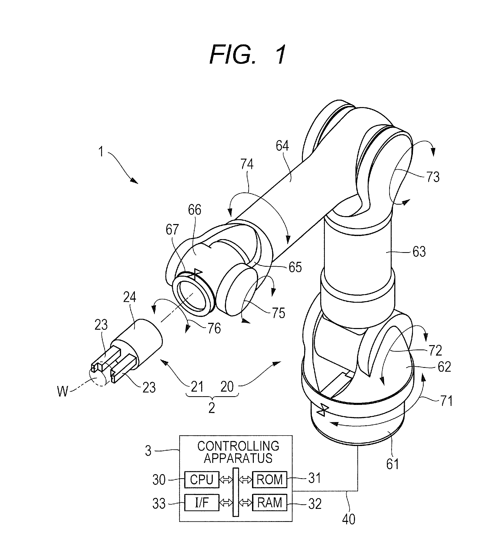
[0030]As shown in FIG. 1, a robot apparatus 1 includes a robot body 2 and a controlling apparatus 3 adapted to control the robot body 2. The robot body 2 is equipped with a hand 21 as an end effector in a front end portion of, for example, a six-axis vertical multi-joint robot arm (hereinafter, referred to as an arm) 20. The arm 20 includes seven links 61 to 67 and six joint driving apparatus 71 to 76 adapted to swingably or pivotably couple together the links 61 to 67.

[0031]The hand 21 is supported by being attached to a foremost link 67 of the arm 20 and is configured such that motion (changes in position and orientation) or a force of the hand 21 will be adjusted by movement of the arm 20. The hand 21 includes a hand body 24 and plural fingers 23 disposed movably with respect to the hand body 24 and configured to be able to grip a workpiece W.

[0032]The controlling apparatus 3 includes a CPU 30 made up of a general purpose microprocessor and the like. The CPU 30 controls movement ...

second embodiment

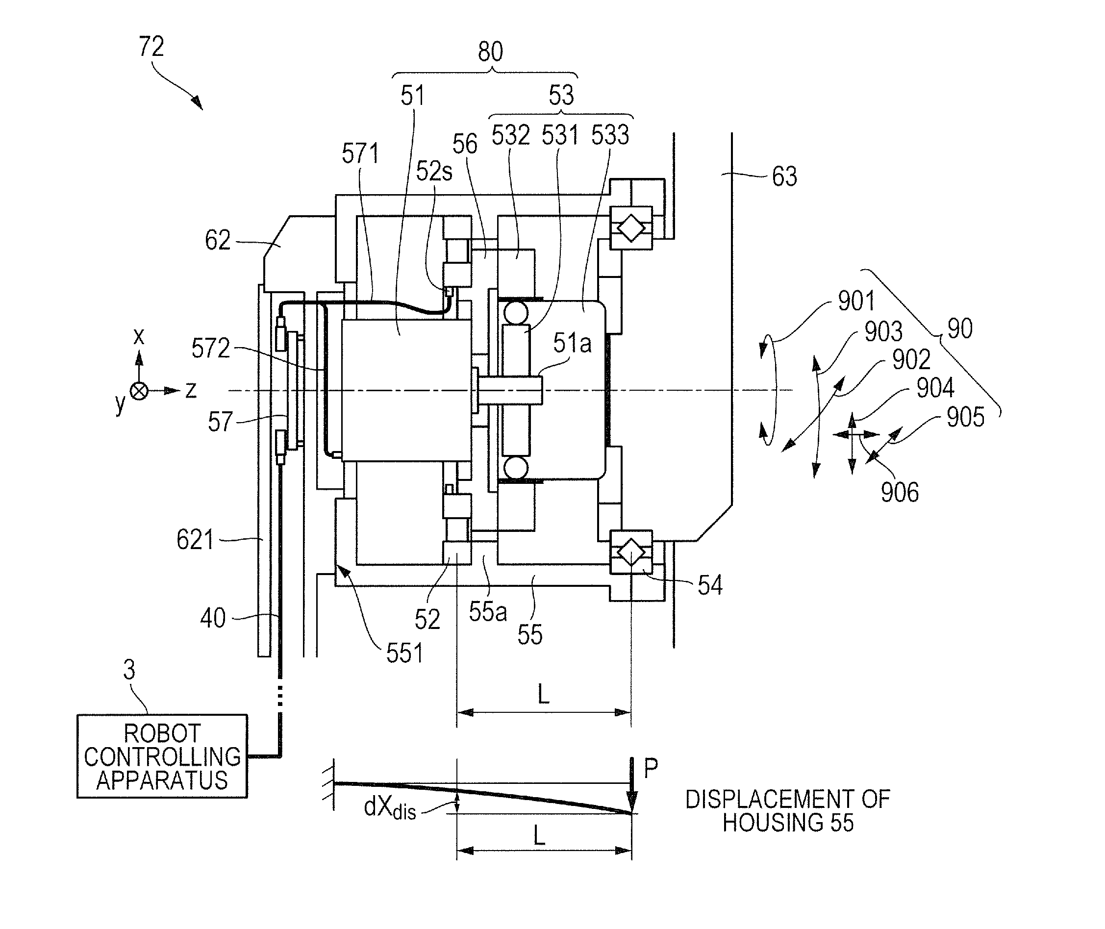
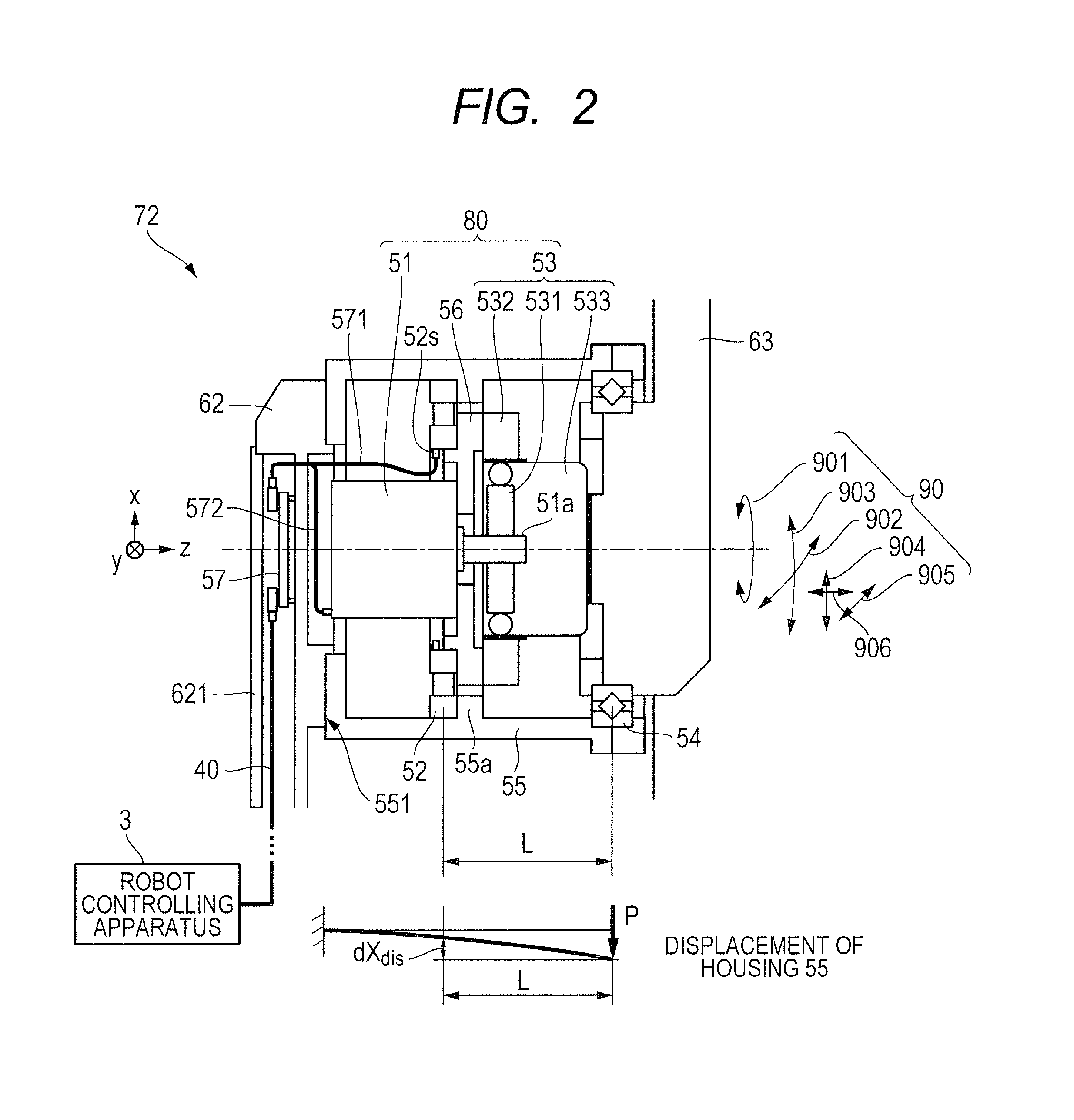
[0090]As shown in FIG. 2 and Expression (3), it can be seen that the deformation amount of the outer ring portion 5211 of the elastic body 521 of the torque detection apparatus 52 is affected greatly by the distance L between the installation location on the housing unit 55 and the bearing 54 supporting the joint. Thus, if the torque detection apparatus 52 (elastic body 521) can be placed close to the bearing 54, an amount of cross-axis interference can be reduced further.

[0091]For example, as shown in FIG. 3, the flange portion 55b used to attach the torque detection apparatus (elastic body 521) to the housing unit 55 is placed closer to the bearing (joint support mechanism) 54 than the flange portion (55a) in FIG. 2. Then, the torque detection apparatus 52 (elastic body 521) is mounted between the fixing portion 532 of the reduction mechanism 53 and the flange portion 55b. The rest of the configuration is similar to FIG. 2.

[0092]In the configuration of FIG. 3, the torque detection...

third embodiment

[0094]In the embodiments described above, the elastic body 521 of the torque detection apparatus 52 has been shown as having an annular shape (ring shape) by example. However, the joint driving apparatus (72) may be configured as shown in FIG. 4 using the torque detection apparatus 52 which employs an elastic body of different shapes such as shown in FIGS. 7 to 9.

[0095]The present embodiment uses a torque detection apparatus 52 such as shown in FIG. 7. The torque detection apparatus 52 includes an elastic body 521, an exterior member (cover) 522 configured to protect the elastic body 521, and a sensor cable 571 and has an approximately cylindrical shape as a whole.

[0096]As shown in FIG. 8, the elastic body 521 includes a flange 5211a serving as a first fixing portion and a flange 5212a serving as a second fixing portion. The flanges 5211a and 5212a are joined together by an elastically deformable portion 5213 cylindrical in shape, and are united into a cross-sectional shape such as ...


PUM


Abstract

The present invention allows a joint driving apparatus of a robot apparatus to measure joint driving torque with high accuracy and perform joint torque control accurately and reliably using a simple, inexpensive, small, lightweight and sturdy configuration without being affected by cross-axis disturbance forces. A joint driving apparatus includes a housing unit fixed to a first link; a bearing mounted in the housing unit and adapted to rotatably support a second link; a driving unit housed in the housing unit and adapted to rotationally drive the second link; a supporting unit installed between the driving unit and the housing unit and adapted to support the driving unit on the housing unit; and a sensor adapted to detect torque generated on the supporting unit.

Description

BACKGROUND OF THE INVENTION[0001]1. Field of the Invention[0002]The present invention relates to a joint driving apparatus provided with a second link pivotally supported on a first link and adapted to control relative orientation of the first and second links as well as to a robot apparatus equipped with the joint driving apparatus.[0003]2. Description of the Related Art[0004]In recent years, articulated robot manipulators have been finding increasingly wider uses and expanding their application to areas, such as collaborative work with humans and assembly work in a factory, in which robots are required to perform flexible movements. A stable and wide-band force control function is required of such a robot apparatus to follow external forces. Thus, there is demand to construct a control system based on joint-level torque control (torque servo) instead of a motion control system based on joint position control (position servo) widely used conventionally. The torque control requires ...

Claims


Application Information

Patent Timeline
Patent Type & Authority Applications(United States)
IPC IPC(8): B25J17/00B25J13/08
CPCB25J13/085B25J17/00B25J9/1633B25J9/126B25J17/0208
Inventor OGATA, MASARU
Owner CANON KK
Why Eureka
Try Eureka