Head and liquid ejecting apparatus

a liquid ejecting apparatus and head technology, applied in piezoelectric/electrostrictive/magnetostrictive devices, piezoelectric/electrostrictive device details, printing, etc., can solve the problems of increasing the cost, reducing the number of boards obtained from one raw material, and ejecting ink, so as to reduce the width reduce the size of the driving circuit board, and reduce the size of the head

Active Publication Date: 2016-09-15
SEIKO EPSON CORP
View PDF2 Cites 5 Cited by
  • Summary
  • Abstract
  • Description
  • Claims
  • Application Information

AI Technical Summary

Benefits of technology

[0014]According to the aspect, the first connection wiring and the second connection wiring are extended to pass through the driving circuit board, and thus it is possible to realize size reduction in the first direction and the second direction. In addition, the common electrode is provided between two piezo element rows. Thus it is sufficient to provide one second bump row which is connected to the common electrode. As a result, it is sufficient to provide three bumps in total including the first bump and the second bump, and thus it is possible to reduce the width of the driving circuit board in the second direction. In this way, it is possible to reduce the size of the driving circuit board, that is, it is possible to reduce the size of the head, and thus the head of the invention can support the nozzle opening with high density and discharge ink with high density.
[0015]Here, in the head according to Aspect 1, it is preferable that the second bump is formed between the piezo element rows. According to this aspect, it is possible to reduce the size of the driving circuit board in the first direction, and thereby to reduce the size of the head.
[0016]In addition, in the head according to Aspect 1 or Aspect 2, it is preferable that the adhesive layer is provided on both sides of the second bump in the second direction. According to this aspect, it is possible to more ensurely maintain the electrical connection between the first bump and the second bump.
[0017]In addition, in the head according to any one of Aspect 1 to Aspect 3, it is preferable that on a surface of the driving circuit board on the actuator substrate side, an accommodating portion having a recessed shape faces the piezo element row and is extended in the second direction, and a wiring is formed in the accommodating portion. According to this aspect, it is possible to provide the wiring in the accommodating portion for various uses, for example, decreasing the electric resistance by connecting the wiring which is provided in the accommodating portion to the wiring having a small current capacity included in the driving circuit. In addition, the wiring can be separated from the piezo element by disposing the wiring in the accommodating portion. With this, it is possible to reduce a risk that displacement of the piezo element is disturbed by the driving circuit board. In addition, it is possible to prevent discharge from occurring between the wiring and the piezo element, and thereby to manufacture the reliable head which protects the piezo element.
[0018]In addition, in the head according to any one of Aspect 1 to Aspect 4, it is preferable that the second bump is extended in the first direction, and at least two second through holes are formed on the outside from both ends of the second bump in the first direction. According to this aspect, it is possible to suppress the variation of the voltage drop of the common electrode by the two second through holes and the two second connection wirings, and to reduce the driving circuit board in the second direction.
[0019]According to this aspect of the invention, there is provided a liquid ejecting apparatus including the head according to any one of Aspect 1 to Aspect 5. According to this aspect, a head and a liquid ejecting apparatus in which, the size of a driving circuit board which forms a holding portion is reduced, are provided and thus it is possible to realize cost reduction.

Problems solved by technology

In addition, if the driving circuit board is enlarged, the number of boards obtained from one raw material is decreased, and thus cost is increased.
In addition, such a problem exists in not only a head for ejecting ink, but also a head for ejecting liquid droplets other than the ink.

Method used


Image

  • Head and liquid ejecting apparatus
  • Head and liquid ejecting apparatus
  • Head and liquid ejecting apparatus

Examples


embodiment 1

[0038]The invention will be specifically described based on embodiments. In the present embodiment, an ink jet recording head will be described as an example of a head.

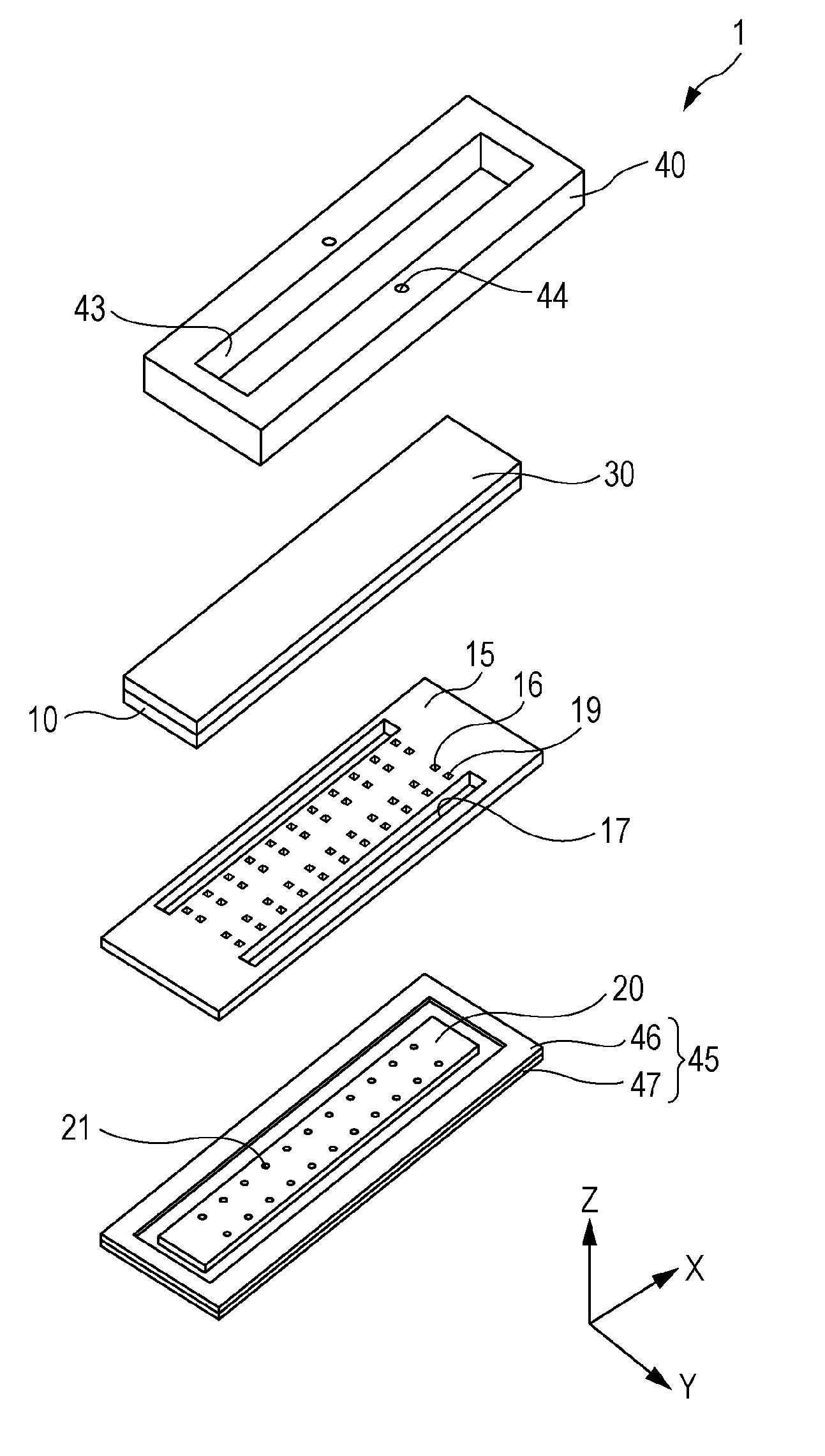
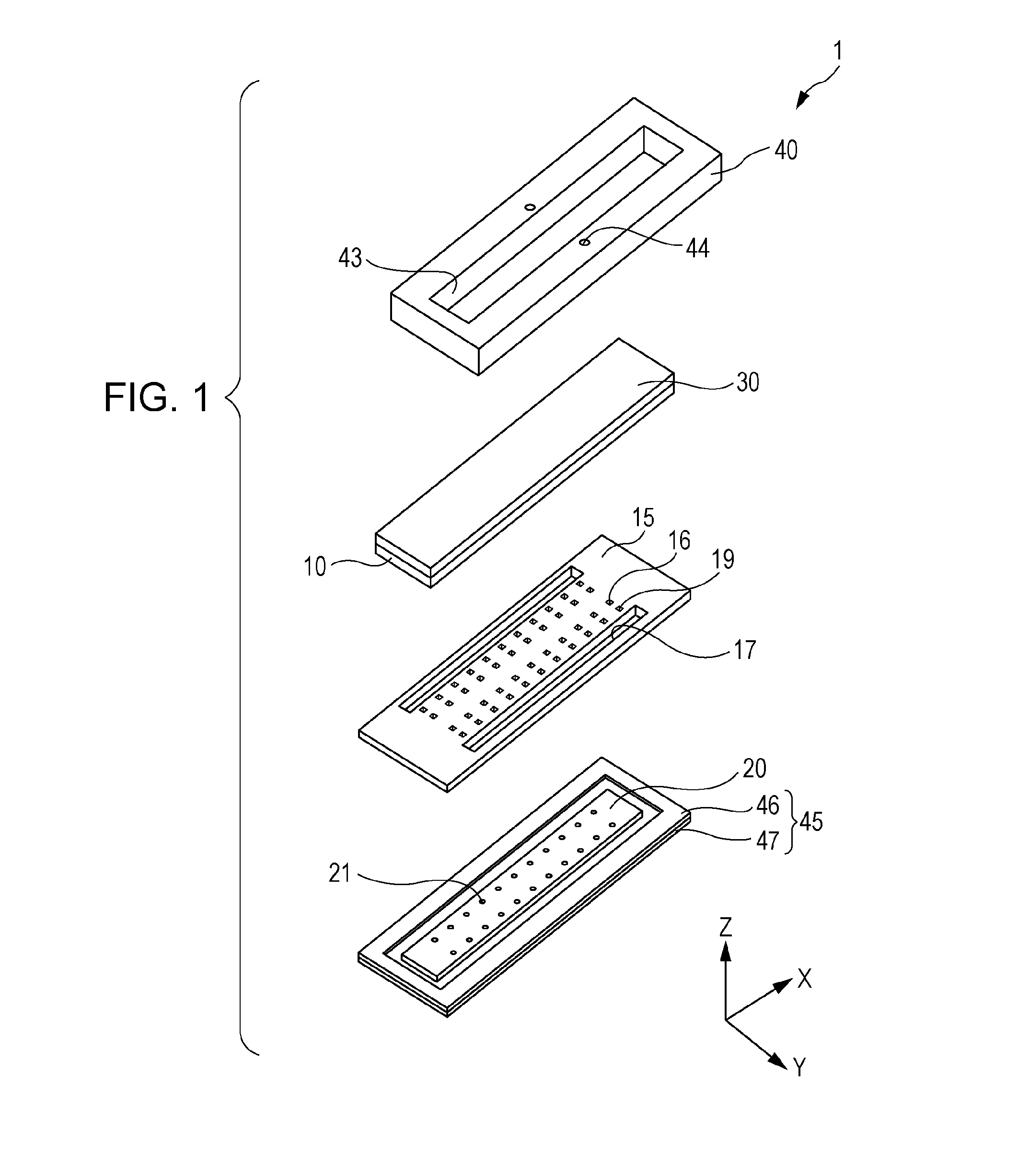
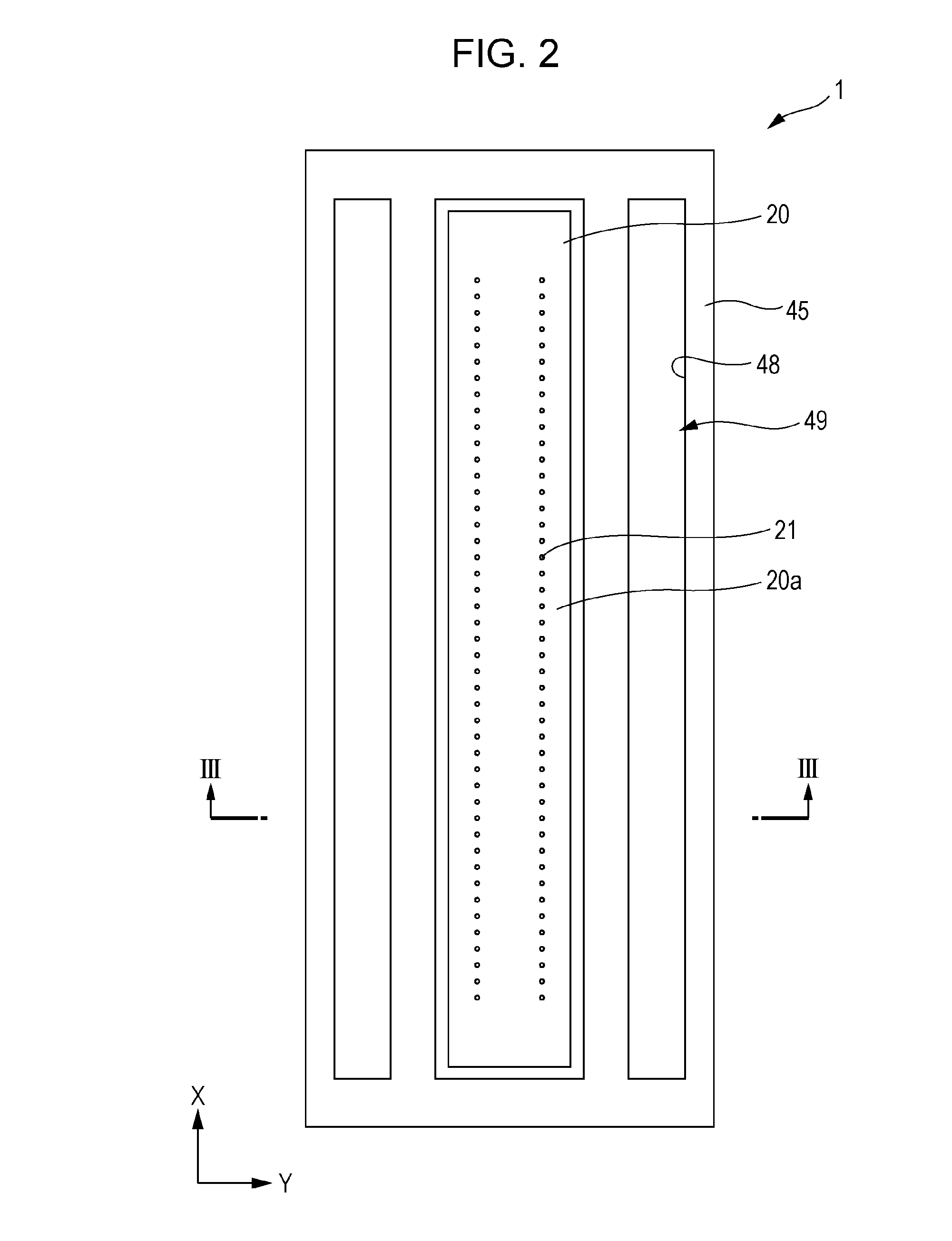
[0039]FIG. 1 is an exploded perspective view of the head according to the embodiment, FIG. 2 is a plan view of the head (a plan view of a liquid ejection surface 20a), FIG. 3 is a sectional view taken along line III-III in FIG. 2, FIG. 4 is a sectional view obtained by enlarging a main portion of FIG. 3, and FIG. 5 is a plan view of a main portion of a channel formation substrate.

[0040]In the embodiment, the head 1 is provided with a plurality of members such as a channel formation substrate 10, a communicating plate 15, a nozzle plate 20, a driving circuit board 30, and a compliance board 45.

[0041]The channel formation substrate 10 can be formed of, for example, metal such as a stainless steel or Ni, a ceramic material such as ZrO2 or Al2O3, a glass ceramic material, and an oxide such as an oxide MgO and LaAlO3. In t...

embodiment 2

[0162]A head 1 in Embodiment 2 is mounted on an ink jet type recoding apparatus which is an example of a liquid ejecting apparatus. FIG. 17 is a schematic view illustrating an example of an ink jet type recoding apparatus.

[0163]In an ink jet type recoding apparatus I, the head 1 is provided with a detachable cartridge 2 forming a supply unit, and a carriage 3 which is mounted on the head 1 is provided to be freely movable in the axial direction of a carriage axis 5 attached to an apparatus main body 4.

[0164]In addition, when a driving force of a driving motor 6 is transferred to the carriage 3 via a plurality of gears (not shown) and the timing belt 7, the carriage 3 mounted on the head 1 is moved along the carriage axis 5. On the other hand, a transporting roller 8 is provided in the apparatus main body 4 as a transporting unit, and a recording sheet S which is a recording medium such as a sheet is transported by the transporting roller 8. Meanwhile, the transporting unit that tran...


PUM


Abstract

A head includes a channel formation substrate having two piezoelectric actuator rows formed thereon, a driving circuit, and a driving circuit board which is provided with a first bump and a second bump, in which the first bump is provided on the outside of the piezoelectric actuator row, an adhesive layer is provided on both sides of the first bump and the second bump, a first through hole and a second through hole are provided on the driving circuit board, a first connection wiring and a second connection wiring are provided in the first through hole and the second through hole, and a first electrode of the piezoelectric actuator is electrically connected to a first connection wiring via the first bump and a second electrode is electrically connected to a second connection wiring via the second bump.

Description

CROSS-REFERENCE TO RELATED APPLICATIONS[0001]The present application claims priority to Japanese Patent Application No. 2015-047693 filed on Mar. 10, 2015, which is hereby incorporated by reference in its entirety.BACKGROUND[0002]1. Technical Field[0003]The present invention relates to a head which ejects a liquid, and a liquid ejecting apparatus which is provided with the head, and particularly relates to an ink jet recording head and an ink jet type recoding apparatus which eject ink as the liquid.[0004]2. Related Art[0005]A piezo ink jet system is an on-demand type ink jet printing system which discharges a liquid droplet by deforming a piezo element through the applying of a voltage to the piezo element (JIS Z8123-1: 2013).[0006]A permanent head is a machine portion or an electrical portion of a printer main body which continuously or intermittently generates a liquid droplet of ink (JIS Z8123-1: 2013).[0007]The permanent head (hereinafter, referred to as a “head”) which is used...

Claims


Application Information

Patent Timeline
Patent Type & Authority Applications(United States)
IPC IPC(8): B41J2/14H01L41/047H01L41/04
CPCB41J2/14201B41J2002/14491H01L41/0471H01L41/042B41J2/01B41J2/14233B41J2/161B41J2/1628B41J2/1629B41J2/1631B41J2/1645B41J2002/14241B41J2202/18H10N30/2047H10N30/871H10N30/802
Inventor HAMAGUCHI, TOSHIAKIHIRAI, EIJUNAGANUMA, YOICHITAKABE, MOTOKI
Owner SEIKO EPSON CORP
Why Eureka
Try Eureka