Magnetic resonance imaging apparatus

Active Publication Date: 2016-09-15
FUJIFILM HEALTHCARE CORP
View PDF14 Cites 3 Cited by
  • Summary
  • Abstract
  • Description
  • Claims
  • Application Information

AI Technical Summary

Benefits of technology

[0011]According to the present invention, because a dynamic range of an NMR signal to be measured is narrowed and reception gain for the said NMR signal can be increased, a ratio of noise superimposed in a reception system can be redu

Problems solved by technology

However, actually, because an A/D converter has a dynamic range limitation, a

Method used


Image

  • Magnetic resonance imaging apparatus
  • Magnetic resonance imaging apparatus
  • Magnetic resonance imaging apparatus

Examples


first embodiment

[0026]Hereinafter, the first embodiment of the present invention will be described in detail according to the attached drawings. Additionally, in all the drawings of the present description, the same reference signs are used for components having the same functions, and the repeated explanations are omitted.

[0027]

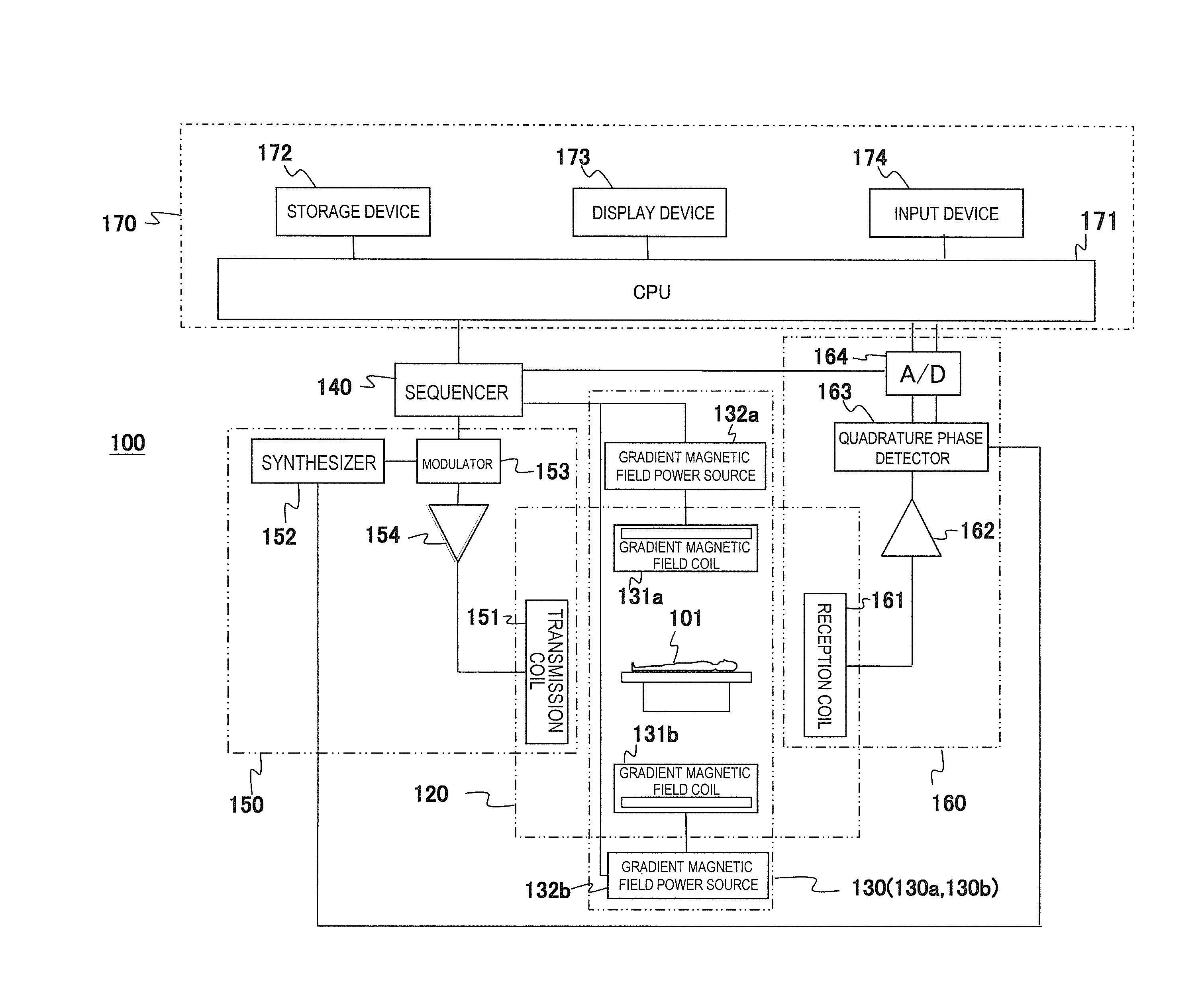
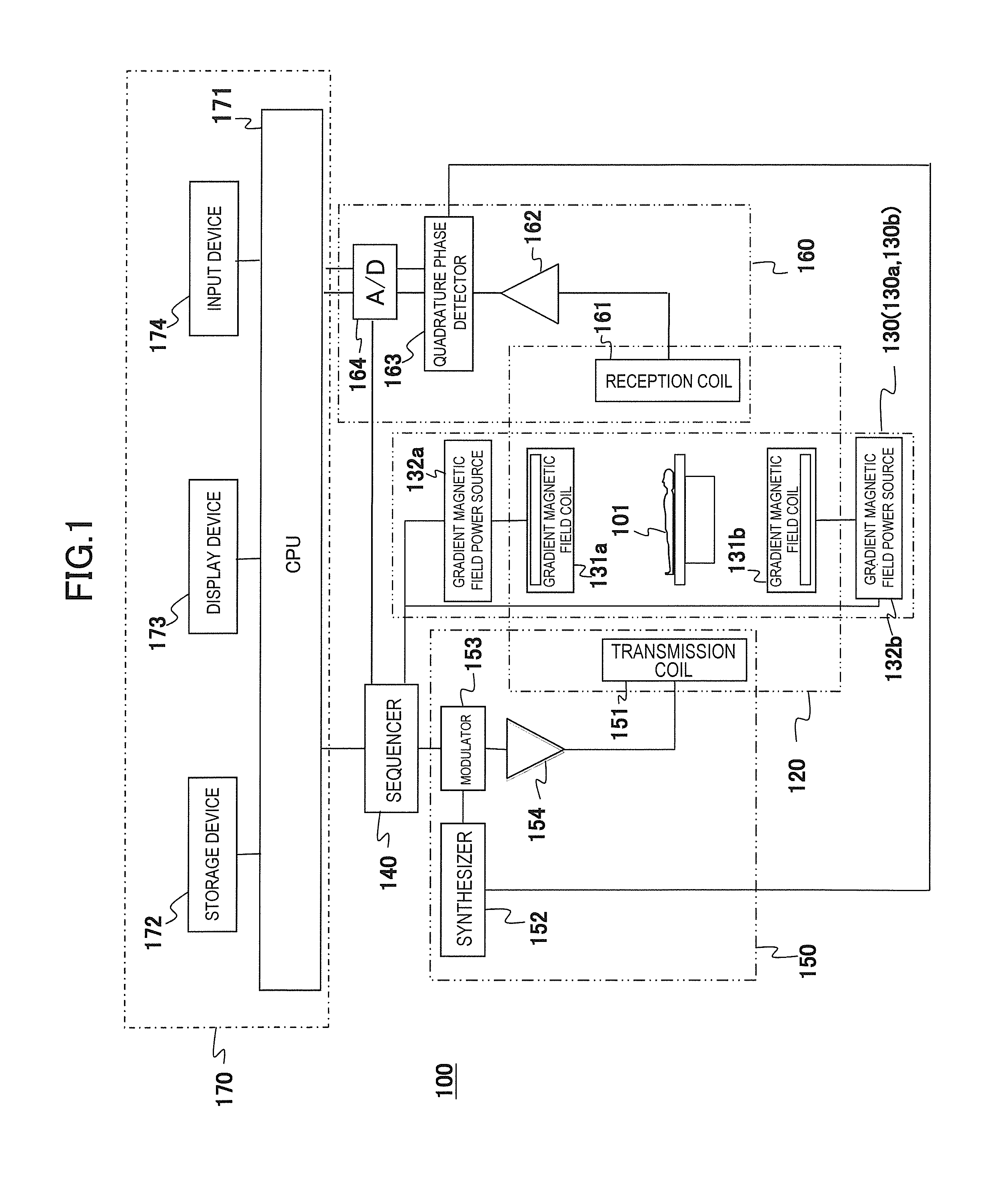
[0028]First, an overview of an example of an MRI apparatus related to the present invention will be described based on FIG. 1. FIG. 1 is a block diagram showing an overall configuration of one embodiment of the MRI apparatus related to the present invention.

[0029]An MRI apparatus 100 of the present embodiment is provided with the gradient magnetic field application unit that applies two or more gradient magnetic field pulses composed of waveforms different from each other according to the spatial position on the gradient magnetic field application axis in an imaging region, and the gradient magnetic field application unit applies gradient magnetic field pulses with two or m...

embodiment

[0090]Here, shown are amplitude profiles of reception NMR signals to be obtained in case of actually driving the two gradient magnetic field coils 131a and 131b at different timings. FIG. 9 shows an amplitude profile 701 of reception NMR signals obtained by shifting between both the timings of supplying driving electric currents to the gradient magnetic field coils 131a and 131b, i.e. timings of applying frequency encoding gradient magnetic field pulses from the gradient magnetic field coils 131a and 131b by 30 μs as well as an amplitude profile 702 reception NMR signals obtained in case of applying the frequency encoding gradient magnetic field pulses without shifting the timings. Also, both the signals were amplified with the same reception gain.

[0091]Also, FIG. 10(a) shows an enlarged display 801 of the center of k-space to be measured in case of shifting an application timing, and FIG. 10(b) shows an enlarged display 802 of the center of k-space to be measured in case of not shi...

second embodiment

[0108]Next, a second embodiment of the present invention will be described. The first embodiment realizes the two gradient magnetic field generating systems 130 using two gradient magnetic field power sources. On the other hand, the present embodiment realizes the two gradient magnetic field generating systems 130 using a single gradient magnetic field power source and a delay circuit.

[0109]Hereinafter, the present embodiment will be described by mainly focusing on a different configuration from the first embodiment.

[0110]

[0111]FIG. 11 is a block diagram of the MRI apparatus 100a of the present embodiment. As shown in the present figure, the gradient magnetic field generating system 130 of the MRI apparatus 100a of the present embodiment comprises the one gradient magnetic field power source 132, a first gradient magnetic field coil 131a, a second gradient magnetic field coil 131b, and a delay circuit 133. The other configuration is similar to the first embodiment.

[0112]

[0113]Simila...


PUM


Abstract

In order to obtain highly accurate images with a high SNR without extending measurement time or increasing hardware costs and software processing costs, the present invention narrows a dynamic range (amplitude) of an NMR signal to be received by a reception coil (reception NMR signal) in an MRI apparatus. In order to narrow the amplitude of the reception NMR signal, according to the position of an imaging region, a peak position of the reception NMR signal is shifted from the said position in the present embodiment. The shift is achieved by applying frequency encoding gradient magnetic field pulses whose application amount in the time direction is different according to the position. This is realized by a plurality of gradient magnetic field generating systems that can be driven independently.

Description

TECHNICAL FIELD[0001]The present invention relates to a magnetic resonance imaging (hereinafter, referred to as MRI) technique for measuring nuclear magnetic resonance signals (hereinafter, referred to as NMR signals) from hydrogen, phosphorus, etc. of an object and imaging nuclear density distribution, relaxation time distribution, etc. and, in particular, to a technique for measuring the NMR signals.BACKGROUND ART[0002]An MRI apparatus measures NMR signals generated by atomic nucleus spins comprising an object, particularly, human tissue to two-dimensionally or three-dimensionally image forms and functions of the head, abdomen, limbs, and the like. In imaging, the object is placed in a static magnetic field (a polarizing magnetic field Bo), a high-frequency magnetic field pulse is applied together with a slice-selective gradient magnetic field pulse in order to selectively excite a certain region, and then an excitation range is encoded to provide positional information by applyin...

Claims


Application Information

Patent Timeline
IPC IPC(8): G01R33/385G01R33/54G01R33/36
CPCG01R33/3852G01R33/543G01R33/36A61B5/055G01R33/3621G01R33/561
Inventor HANADA, HIKARU
Owner FUJIFILM HEALTHCARE CORP
Why Eureka
Try Eureka