Method for monitoring a patient within a medical monitoring area

a monitoring area and patient technology, applied in the field of monitoring a patient within a medical monitoring area, can solve the problems of patient injury, patient deterioration, and patients who are classified as bedridden, and achieve the effects of detecting the quality of sedation even more accurately, improving monitoring, and reducing activity

Active Publication Date: 2016-09-15
DRAGERWERK AG
View PDF7 Cites 69 Cited by
  • Summary
  • Abstract
  • Description
  • Claims
  • Application Information

AI Technical Summary

Benefits of technology

[0036]A method according to the above paragraph may be perfected in such a way that in case of a first-time motion of the detected object in the form of a person beyond the location boundary, this person is defined as a patient. As was likewise explained above, it an advantage of the present invention that additional information can be assigned to individual objects in the form of persons. Thus, persons may be initially defined, e.g., as patients and they also continue to be defined as patients over the monitoring period due to the tracking of the locations of this person. For example, a location boundary may be placed around the bed in a patient room in the monitoring area. If a person crosses this location boundary and correspondingly gets into the bed in the patient room, it may be assumed with a high degree of probability that this person is a patient. Coupling with a minimum direction of crossing the location boundary may, of course, also be performed in order to also define the correct person as a patient with a higher level of safety. The fact that a bed with a person lying in it in a patient room may also be used to define the person located in it as a patient.
[0037]Another advantage is achieved if the steps of the method are performed in a method according to the present invention according to the above two paragraphs only for the section of the location of the monitoring area on the side of the location boundary on which the detected object is located. This is also an additional functionality of the “virtual fence” monitoring function. It becomes possible in this manner to reduce the section of the monitoring area that is actually being monitored, so that the necessary data sets and the corresponding analysis can correspondingly be reduced. If, for example, an inner area in the monitoring area is defined as the bed, the subsequent monitoring of the patient can be limited to the area within the location boundary around the bed in case of a patient who has laid down in the bed. The reduction of the data set may relate here to the generation of the point cloud, on the one hand, and to the analysis of said point cloud to create the scenario, on the other hand.
[0038]Moreover, a further monitoring functionality is possible in case of a design of the method according to the present invention. Thus, sedation monitoring can be performed, which monitors the sedation and hence the immobilization of a patient. This also preferably involves the use of absolute predefined values in the sense of the present invention.
[0039]It may thus already be advantageous if the at least one absolute predefined value in a method according to the present invention is a maximum and / or minimum change in the location of the detected object over time. In other words, even the gradient of the change over time is preferably monitored, so that an activity index can be generated, which is correlated with the actual activity of the patient. The patient in question may be monitored as a whole or individual limbs of the patient may be monitored as partial objects of the person. The activity index is consequently used to detect the actual activity of individual body parts and thus to infer the current activity situation of the patient. It thus becomes possible that the current activity is related to the desired sedation. If a patient is provided with intense sedation, a lower activity is also correspondingly presumed. If, however, a higher activity, i.e., a greater change in the locations of the object over time can, on the contrary, be detected compared to a preset activity, the dosage of the sedation must be assumed to be very likely to be too low. A corresponding alarm may likewise be generated in this case. For example, individual points of the skeleton of a person can be detected as partial objects of this person in the point cloud. The activity index becomes even more accurate and detailed in this manner and it becomes possible to detect the quality of sedation even more accurately and in more detail. A so-called delirium monitoring functionality may, of course, also be made available based on the activity index in the opposite way. It also becomes possible to detect a person, who becomes too calm in an undesired manner, i.e., for example, becomes comatose. It becomes clearly visible here that the monitoring functionality of the sedation monitoring and the monitoring functionality of delirium monitoring are preferably used combined with one another. Any desired number of limits can be set here to make available an alarm in the particular direction, i.e., for example, in the direction of sufficient sedation and delirium monitoring.
[0040]It may, furthermore, be advantageous in sedation monitoring according to the above paragraph if the predefined and detected object is at least one body part of a person in the method according to the present invention. It can be assumed here, in particular, that the extremities of the person in the form of fingers, hands, arms or legs represent the best predictive value concerning the current activity index. The eyelids of the person may also be monitored, e.g., in case of a corresponding resolution of the depth camera device. It thus becomes possible to achieve an even further improvement of a sedation monitoring as a monitoring functionality of a method according to the present invention.
[0041]It may, moreover, be advantageous in sedation monitoring as a functionality of a method according to the present invention if the absolute predefined value can be set in the form of the maximum and / or minimum change in the location of the detected object. Thus, sedation of a patient may take place in different quantities. For example, a person can be completely immobilized, so that it can be assumed that there is essentially no activity whatsoever. An only mild sedation may also ensure calming of a patient, who otherwise has an only slightly slowed-down activity. To improve the monitoring and to avoid false alarms, the activity index or even directly the respective predefined values may be set for the corresponding maximum or minimum change of the location of the detected object.

Problems solved by technology

It is thus problematic, for example, that confused patients frequently act against medical advice.
In addition, there is a risk that patients who are classified as bedridden leave the bed and are injured.
There also is a risk of seizures, so that the patient may additionally become medically compromised.
It is extraordinarily labor-intensive to keep the above-mentioned risks under control or to reduce them.
This is associated with very high costs, so that this is actually guaranteed in extremely rare cases only.
However, a relatively heavy use of manpower is still necessary in this case as well, because this monitoring must usually be carried out without interruptions 24 hours a day and 7 days a week.
In particular, inattentiveness or tiredness of the monitoring person leads to an incalculable increase in the risk for the patient.
Another drawback is the fact that the private sphere of the patient, relatives or coworkers is compromised.

Method used


Image

  • Method for monitoring a patient within a medical monitoring area
  • Method for monitoring a patient within a medical monitoring area
  • Method for monitoring a patient within a medical monitoring area

Examples


Embodiment Construction

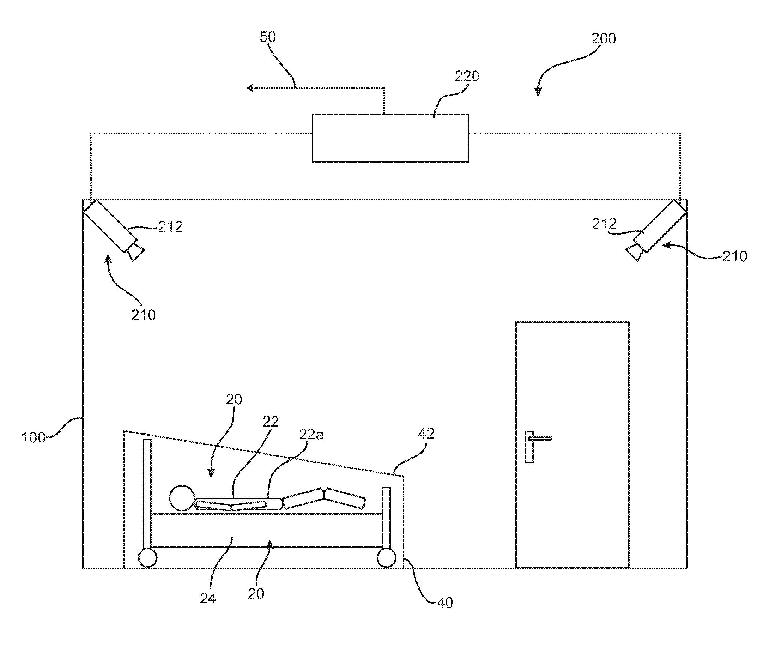
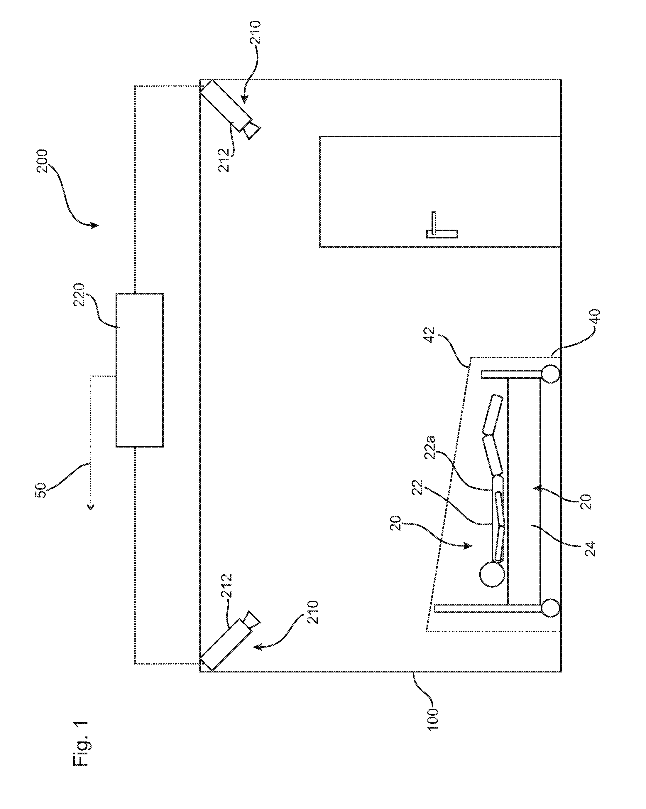
[0082]FIGS. 1 and 2 schematically show a monitoring area 100 in the form of a patient room. A monitoring system 200 with a control unit 220 for carrying out a method according to the present invention can be clearly seen. The monitoring system 200 is equipped, further, with a depth camera device 210 with two depth cameras 212 each. Depending on the monitoring functionalities switched on, a great variety of alarms 50 can be triggered by the control unit 220, The alarm may be transmitted, e.g., to an emergency call system of a pager of a physician or into a monitoring room of a hospital. Storage for documentation purposes or for transmission to an IT system of the hospital is also conceivable.

[0083]As can be clearly seen in FIG. 1, an object 20 in the form of a bed 24 is arranged within the monitoring area 100. An object 20 in the form of a person 22 is located within the bed 24. This person 22 has gotten into the bed or was laid into the bed or was moved with the bed into the room an...


PUM


Abstract

A method for monitoring a patient (22a) within a medical monitoring area (100) by means of a monitoring system (200) with a depth camera device (210). The method includes the following steps:generating a point cloud (30) of the monitoring area (100) with the monitoring system (200);analyzing the point cloud (30) for detecting predefined objects (20), especially persons (22);determining a location of at least one detected object (20) in the monitoring area (100); andcomparing the determined location of the at least one detected object (20) with at least one predefined value (40) for the location of this detected object (20).

Description

CROSS REFERENCE TO RELATED APPLICATIONS[0001]This application is a United States National Phase Application of International Application PCT / EP2014 / 002788 filed Oct. 16, 2014 and claims the benefit of priority under 35 U.S.C. §119 of German Patent Application 10 2013 017 264.0 filed Oct. 17, 2013 the entire contents of which are incorporated herein by reference.FIELD OF THE INVENTION[0002]The present invention pertains to a method for monitoring a patient within a medical monitoring area as well as to a monitoring system for carrying out such a method.BACKGROUND OF THE INVENTION[0003]It is known, in principle, that patients must be subjected to monitoring. For example, the intensity with which the monitoring must be designed depends on the particular medical situation of the patient. It is thus problematic, for example, that confused patients frequently act against medical advice. For example, patients who are provided with a tube and are in a confused mental state tend to remove th...

Claims


Application Information

Patent Timeline
Patent Type & Authority Applications(United States)
IPC IPC(8): G06K9/00A61B5/107A61B5/11G08B21/02A61B5/00
CPCG06K9/00771G08B21/0263A61B5/0077A61B2576/00A61B5/1077A61B5/1079A61B5/1128A61B5/1113G08B21/22G08B25/002G08B25/006G06V20/52
Inventor FRANZ, FRANKSCHLICHTING, STEFAN
Owner DRAGERWERK AG
Why Eureka
Try Eureka