Tiled display and method of assembling same

a technology of tiled display and assembling method, which is applied in the field of displays, can solve the problems of cumbersome fastening means and support structures, still present challenges, and large, and achieve the effects of improving the modularity of the proposed tiled display system, reducing the difficulty of assembly, and substantial variation of pixel pitch

Active Publication Date: 2016-09-15
BARCO NV
View PDF10 Cites 50 Cited by
  • Summary
  • Abstract
  • Description
  • Claims
  • Application Information

AI Technical Summary

Benefits of technology

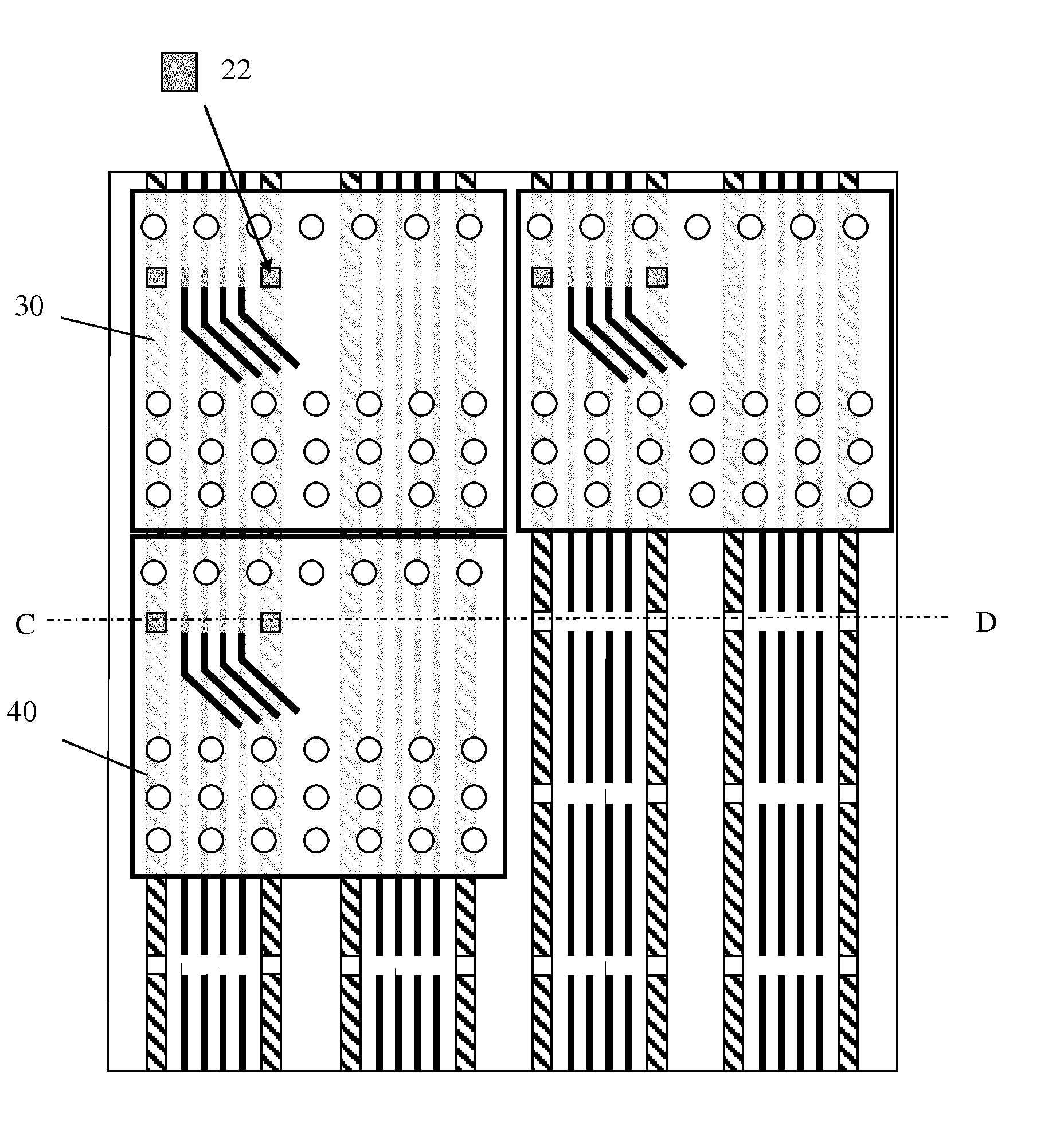
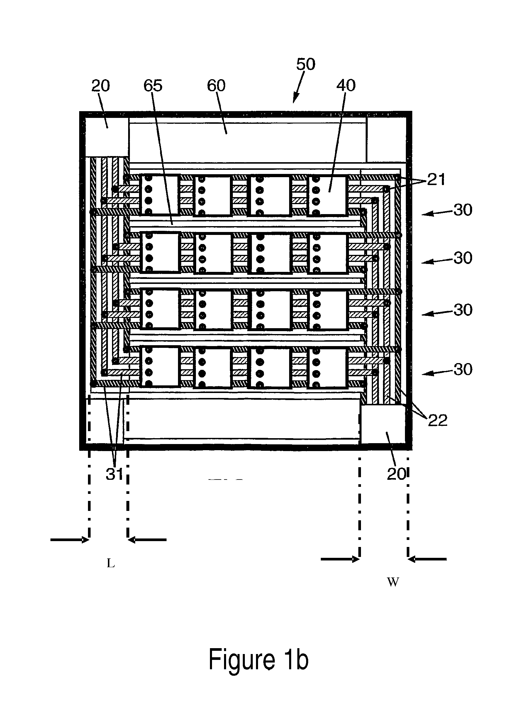
[0039]In that case, it is advantageous (as explained for the contacts between tracks on the carrier substrate and the tiles) to have the tracks interrupted at regular intervals. Modularity of the proposed tiled display system will also be further improved if the distance between two consecutive interruptions is smaller or equal to the length of carrier substrate under any of the display tile connected to the conductive tracks.
[0040]The full advantage of the proposed invention is obtained when the tiles are identical to each other (at least those at the same level on the same and adjacent carrier substrate).
[0041]A further advantage of a tiled display system according to this invention is that a display tile can be cut along a line separating two sets of tracks carrying the power, control and data signals, thereby allowing the realization of a tiled display with a lateral dimension that is substantially equal to an integer number of times the width of a carrier substrate even if one or more of the tiles assembled on the carrier substrates extending over the edge of a carrier substrate. This further advantage is

Problems solved by technology

They offer solutions to simplify assembly and maintenance of such displays but these solutions still present challenges at the time of assembly and disassembly.
While the solutions proposed in both documents simplify the assembly and servicing of the display element, both the fastening means and the support structure remain cumbersome.
One of the disadvantages of conventional LED display screens is that they are large, thick and heavy.
These conventional LED display screens are made of rigid PCB and can only be mounted on flat surfaces.
The number of cables may make the resulting structure very cumbersome.
To make things worse, thermal expansion can cause the seams to evolve differently across the screen with serious consequences for the visual perception of the displayed image.
For a tiled display, obtaining colour and brightness uniformity is often even more difficult, because the tiles and their seams form a regular structure, which is very easily detected by the human eye.
Each strip will also have to be connected to a controller or the strips will have to be daisy-chained with ad-hoc cabling that is likely to be as cumbersome as that of the solutions previously described.
The control of the pixel pitch bet

Method used


Image

  • Tiled display and method of assembling same
  • Tiled display and method of assembling same
  • Tiled display and method of assembling same

Examples


Embodiment Construction

[0081]FIGS. 2a and 2b show a flexible substrate 10 with electrically conducting tracks 20 according to an embodiment of the invention. Each one of the conducting tracks is meant to carry power, data or control signals to LED tiles. For instance, power is conducted through the GND and VSS tracks. The other tracks carry a DATA CLCK signal, DATA (or Video Signal) and COMMAND SIGNAL (the signals considered in e.g. U.S. Pat. No. 7,102,601 to control a tiled LED display; U.S. Pat. No. 7,102,601 is assigned to the present applicant, and its contents, including in particular the description of FIG. 2 therein, are incorporate herein by reference for the purpose of describing the cited signals). The tracks carrying DATA CLCK, DATA and COMMAND SIGNAL may be interrupted at regular intervals as will be discussed in more detail further below.

[0082]In a first preferred embodiment, the conducting tracks 20 are positioned between a first material layer 11 and a second material layer 12. The first an...


PUM


Abstract

A tiled display having discrete luminous sources distributed over at least two adjacent flexible display tiles, each arranged to drive the discrete luminous sources on it when connected to a power supply and when receiving data and control signals; where the power, data and control signals are provided to the tiles trough conducting tracks formed on a carrier substrate, where at least one of the conducting tracks extends from one edge of the carrier substrate to the opposite edge of the carrier substrate.

Description

FIELD OF THE INVENTION[0001]The present invention pertains to the field of displays, in particular to the field of tiled displays.BACKGROUND[0002]As exemplified by the LED display described in the prior art and in particular U.S. Pat. No. 5,900,850, typical large tiled display devices require bulky structures to support the display tiles and keep them aligned.[0003]U.S. Pat. No. 8,434,963, assigned to ORBUS, and EP 2 459 888 A1, in the name of the present applicant, give other examples of metallic support structure made of pultruded beams. Both documents describe solutions to problems such as axial and planar alignment of display tiles and illustrate problems such as assembly and disassembly of the support structure and concealment of the support structure.[0004]US 2010 / 0135032 and US 2007 / 0218751, both assigned to Element Labs, Inc., are more particularly concerned by hanging tiled displays. They offer solutions to simplify assembly and maintenance of such displays but these soluti...

Claims


Application Information

Patent Timeline
IPC IPC(8): G09G3/32G06F3/14
CPCG09G3/32G06F3/1446G09G2330/02G09G2380/02G09G2300/026G09G2300/0426H10K59/18G09F9/301G09F9/3026H05K5/0021H05K5/0247
Inventor MEERSMAN, KARIMDEVOS, BRUNO
Owner BARCO NV
Why Eureka
Try Eureka