Method of manufacturing light-emitting device

a technology of light-emitting devices and manufacturing methods, which is applied in the direction of solid-state devices, electric lighting sources, electric light sources, etc., can solve the problems of uneven emission color of light-emitting devices, and achieve the effect of reducing uneven emission color

Active Publication Date: 2016-09-15
TOYODA GOSEI CO LTD
View PDF7 Cites 11 Cited by
  • Summary
  • Abstract
  • Description
  • Claims
  • Application Information

AI Technical Summary

Benefits of technology

[0021]According to an embodiment of the invention, a light-emitting device can be provided that unevenness in emission color is reduced by precipitating the plural types of phosphor particles at predetermined positions in the sealing material so as not to have the uneven precipitation.

Problems solved by technology

If the method of decreasing the viscosity of the scaling resin by heating is used for precipitating the plural types of phosphor particles in the sealing resin, uneven precipitation may occur since the degree of precipitation is different in each type of phosphor particle, resulting in unevenness in emission color of the light-emitting device.

Method used


Image

  • Method of manufacturing light-emitting device
  • Method of manufacturing light-emitting device
  • Method of manufacturing light-emitting device

Examples


first embodiment

Configuration of Light-Emitting Device

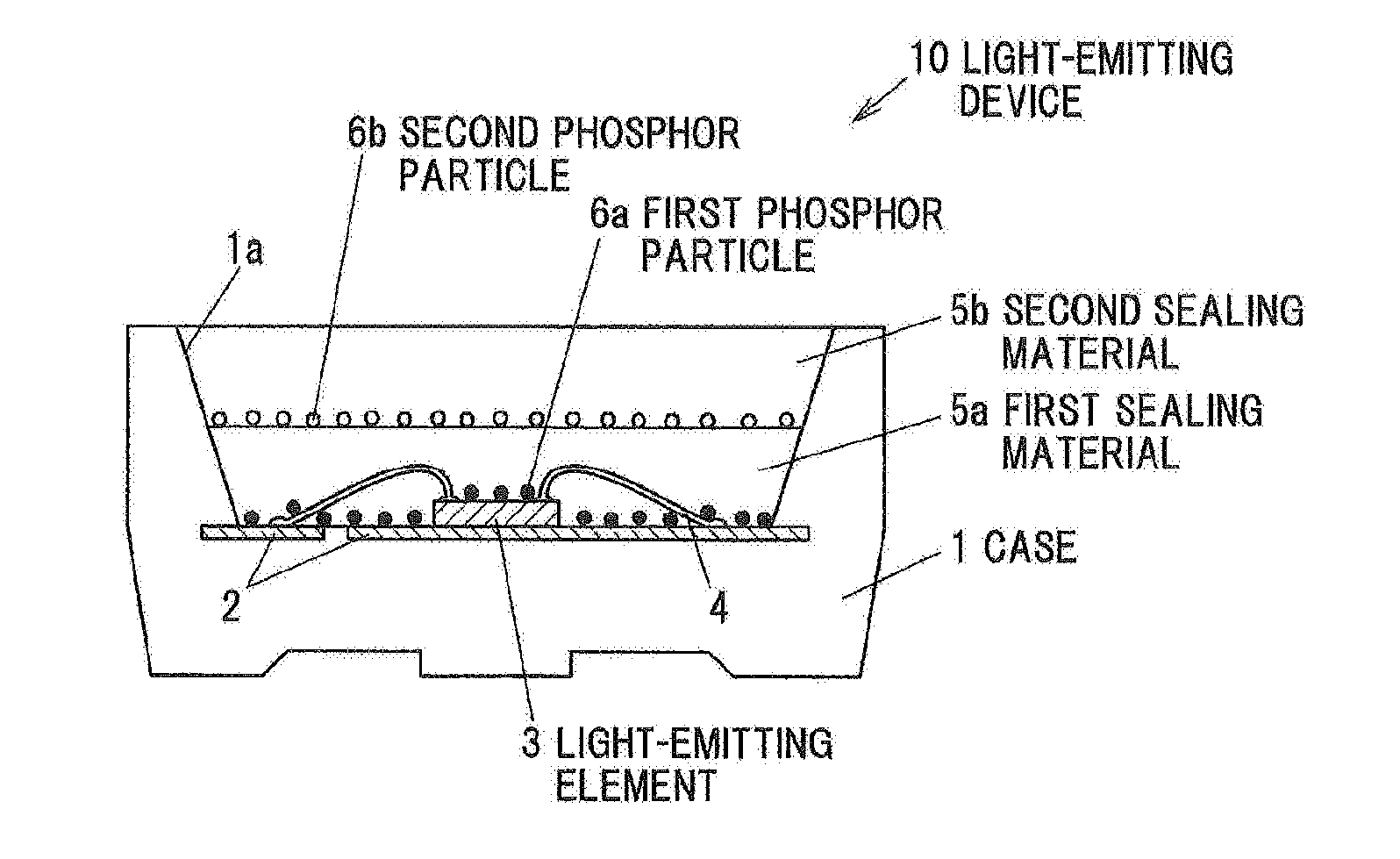
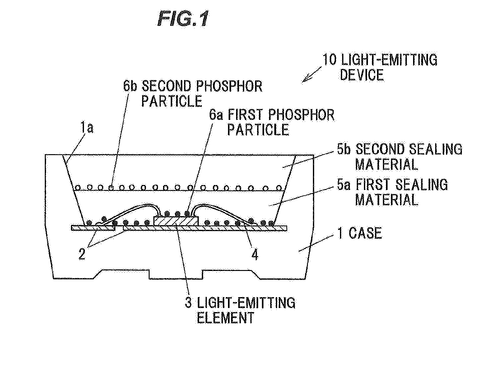
[0029]FIG. 1A is a perspective view showing a light-emitting device 10 in the first embodiment. The light-emitting device 10 has a case 1 having a recessed portion 1a, a base 2 housed in the case 1 so that an upper surface is exposed on the bottom of the recessed portion 1a, a light-emitting element 3 mounted on the base 2, a first sealing material 5a and a second sealing material 5b filled in the recessed portion 1a to seal the light-emitting element 3, and first phosphor particles 6a and second phosphor particles 6b respectively included in the first sealing material 5a and the second sealing material 5b.

[0030]The case 1 is formed of, e.g., a thermoplastic resin such as polyphthalamide resin, LCP (liquid crystal polymer) or PCT (polycyclohexylene dimethylene terephalate), or a thermosetting resin such as silicone resin, modified silicone resin, epoxy resin or modified epoxy resin. The case 1 may include light-reflecting particles of titanium d...

second embodiment

Configuration of Light-Emitting Device

[0048]FIG. 3 is a vertical cross sectional view showing a light-emitting device 20 in the second embodiment. The light-emitting device 20 is different from the light-emitting device 10 of the first embodiment mainly in that a first sealing material 25a including a dispersant is provided and the first phosphor particles 6a in the first sealing material 25a hardly precipitate. Note that, the explanation of the same features as the light-emitting device 10 in the first embodiment will be omitted or simplified.

[0049]The first sealing material 25a includes a dispersant for improving dispersibility of the first phosphor particles 6a The dispersant is, e.g., particles of silica such as AEROSIL™.

[0050]The base material of the first sealing material 25a can be the same material as the first sealing material 5a in the first embodiment but is particularly preferably an organically modified silicone. Since the viscosity of the organically modified silicone ...

third embodiment

Configuration of Light-Emitting Device

[0059]FIG. 5 is a vertical cross sectional view showing a light-emitting device 30 in the third embodiment. The light-emitting device 30 is different from the light-emitting device 10 of the first embodiment mainly in that at least some of the second phosphor particles 6b precipitate in the first sealing material 5a. Note that, the explanation of the same features as the light-emitting device 10 in the first embodiment will be omitted or simplified.

[0060]In the light-emitting device 30, relatively large particles (particles having a particle size of at least more than D50, preferably not less than D90) of the first phosphor particles 6a precipitate close to the bottom of the first sealing material 5a, and at least some of relatively large particles (particles having a particle size of at least more than D50, preferably not less than D90) of the second phosphor particles 6b precipitate in the first sealing material 5a.

[0061]FIG. 5 shows a state ...


PUM


Abstract

A method of manufacturing a light-emitting device includes providing a case including a recessed portion and mounting a light-emitting element on a bottom of the recessed portion, putting a first sealing material including a first phosphor particle into the recessed portion, putting a second sealing material including a second phosphor particle on the first sealing material in the recessed portion, and precipitating the second phosphor particle before the second sealing material cures. The second phosphor particle is located above the first phosphor particle after the first and second sealing materials cure.

Description

[0001]The present application is based on Japanese patent application No. 2015-045876 filed on Mar. 9, 2015, the entire contents of which are incorporated herein by reference.BACKGROUND OF THE INVENTION[0002]1. Field of the Invention[0003]The invention relates to a method of manufacturing a light-emitting device.[0004]2. Description of the Related Art[0005]A light-emitting device is known in which plural types of phosphors are each located in different layers in a sealing resin (see e.g. IP-A-2007-49114).[0006]Also, a method of manufacturing a light-emitting device is known in which a sealing resin is heated so as to decrease the viscosity of the sealing resin to precipitate phosphor particles included in the sealing resin (see e.g. JP-A-2008-103688).SUMMARY OF THE INVENTION[0007]If the method of decreasing the viscosity of the scaling resin by heating is used for precipitating the plural types of phosphor particles in the sealing resin, uneven precipitation may occur since the degr...

Claims


Application Information

Patent Timeline
Patent Type & Authority Applications(United States)
IPC IPC(8): H01L33/50H01L33/54
CPCH01L33/504H01L33/54H01L2933/005H01L2933/0041H01L33/501H01L33/508H01L2224/48091H05B33/10H05B33/04H01L2924/00014H01L2924/181
Inventor MORIMURA, YUTAITO, YUHKI
Owner TOYODA GOSEI CO LTD
Why Eureka
Try Eureka