Armature for an electric machine

a technology of electric machines and armatures, which is applied in the direction of windings conductor shapes/forms/construction, etc., can solve the problems of increasing the demand for induction machines that do not use magnets, steep rises in magnet costs, etc., and achieves the reduction of bending radius, reducing takt time, and reducing the number of welded points

Active Publication Date: 2016-09-15
MITSUBISHI ELECTRIC CORP
View PDF6 Cites 14 Cited by
  • Summary
  • Abstract
  • Description
  • Claims
  • Application Information

AI Technical Summary

Benefits of technology

[0016]According to the present invention, because two-lane winding bodies that are produced by stacking and winding two conductor wires are mounted into three slots that line up consecutively in a direction of slot arrangement at an angular spacing of p slots, the amount of displacement at the top portions of the coil end portions is double the width of the conductor wires in the slot depth direction. Thus, the bending radius is reduced when shaping the top portions of the coil end portions into crank shapes by bending compared to when hexagonal coils are used, enabling radial dimensions and axial dimensions of the coil ends to be reduced.
[0017]Because the two-lane winding bodies 221 are produced so as to be mounted into three slots that line up consecutively in the direction of slot arrangement at an angular spacing of p slots, the number of welded points is reduced compared to coil segments, reducing takt time during production, and also suppressing the occurrence of quality problems.
[0018]Because the armature winding can be produced by assembling the two-lane winding bodies sequentially from the direction of slot arrangement, the complicated step of interweaving wave-wound coils is no longer required, increasing productivity.
[0019]Because the conductor wires that constitute the two-lane winding bodies are wound so as to cycle among three slots by being folded back at second and third slots that are positioned on two sides of a first slot, the directions in which the coil end portions are displaced in a slot depth direction alternate. Thus, positions at which different-phase coil end portions, where electric potential differences are comparatively large, approach each other in the slot depth direction are reduced, reducing the risk that dielectric breakdown may occur.

Problems solved by technology

In addition, demand for induction machines that do not use magnets has also increased due to steep rises in magnet costs, and there is demand for armatures that use armature windings that have higher-efficiency distributed winding constructions.

Method used


Image

  • Armature for an electric machine
  • Armature for an electric machine
  • Armature for an electric machine

Examples


embodiment 1

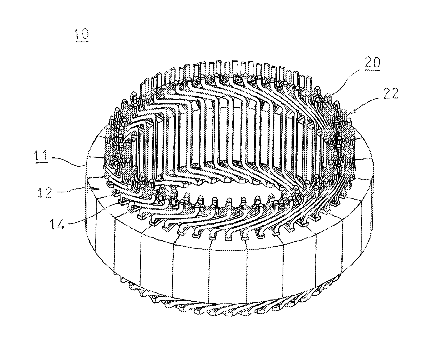
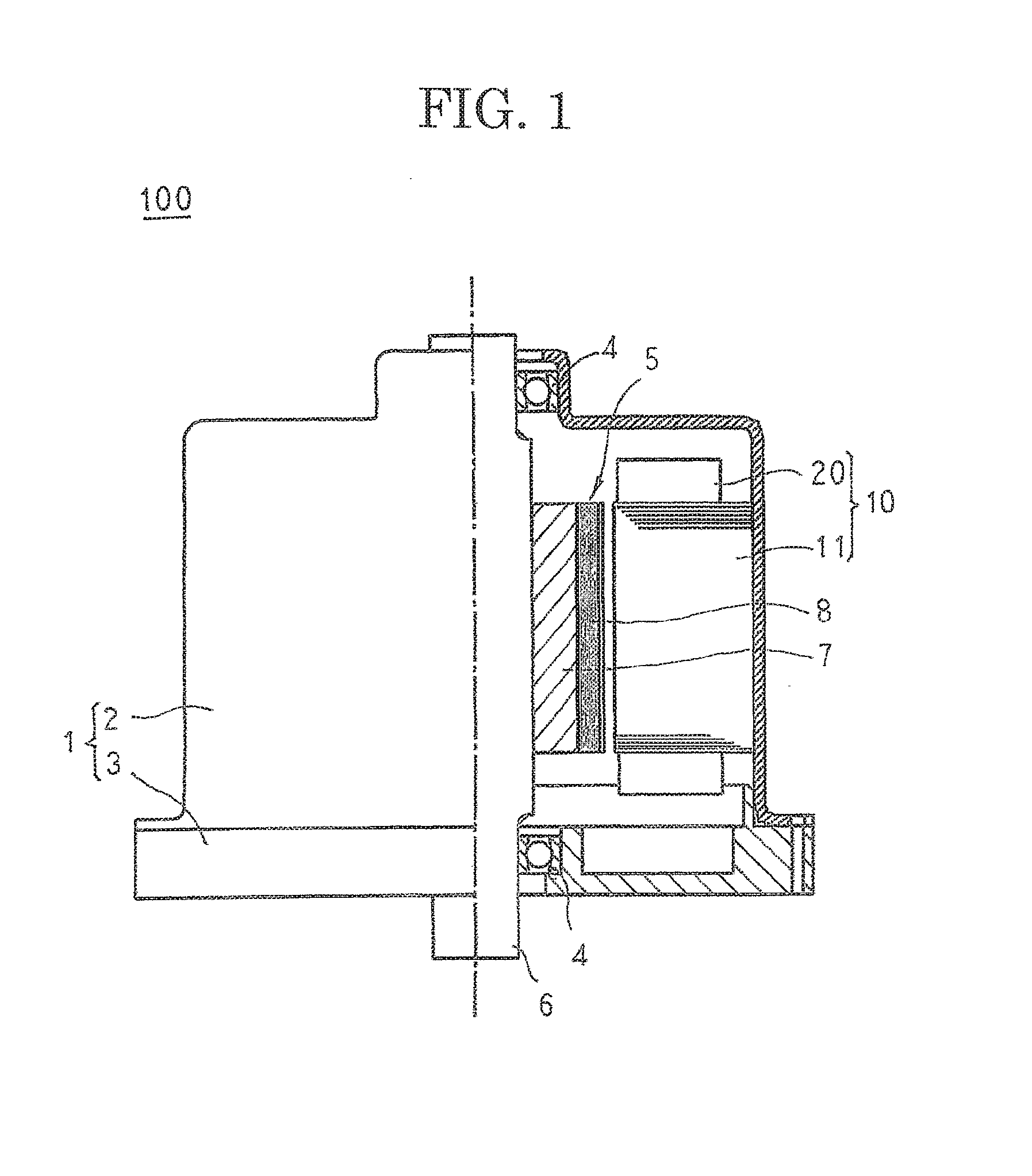
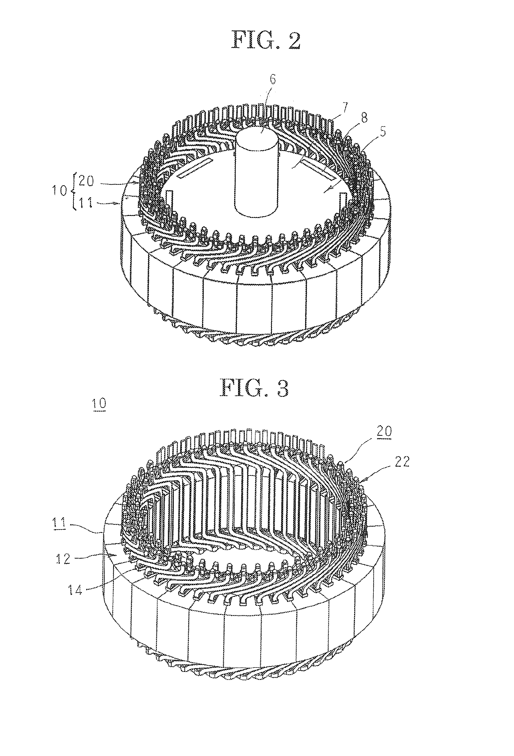
[0050]FIG. 1 is a half section that shows a rotary electric machine according to Embodiment 1 of the present invention, FIG. 2 is an oblique projection that shows part of the rotary electric machine according to Embodiment 1 of the present invention, FIG. 3 is an oblique projection that shows an armature that is used in the rotary electric machine according to Embodiment 1 of the present invention, FIG. 4 is an oblique projection that shows a core block that constitutes part of the armature that is used in the rotary electric machine according to Embodiment 1 of the present invention, FIG. 5 is an oblique projection that shows a two-lane winding body that constitutes part of an armature winding in the rotary electric machine according to Embodiment 1 of the present invention, FIG. 6 is an end elevation that shows the two-lane winding body that constitutes part of the armature winding in the rotary electric machine according to Embodiment 1 of the present invention, FIG. 7 is a front...

embodiment 2

[0087]FIG. 23 is an end elevation that schematically shows a two-lane winding body that constitutes part of an armature winding in a rotary electric machine according to Embodiment 2 of the present invention. Moreover, coil end portions are represented as straight lines in FIG. 23.

[0088]In FIG. 23, a two-lane winding body 22A is produced into a coil pattern in which two conductor wires 19 are wound into an edgewise winding so as to be stacked in a short-side direction, and in a third slot, a first slot, and a second slot that line up consecutively in a circumferential direction so as to be separated by an angular pitch of six slots, are inserted sequentially into the first slot, the second slot, the first slot, the third slot, the first slot, and the second slot.

[0089]Moreover, the rest of the configuration is configured in a similar or identical manner to that of Embodiment 1 above except that the two-lane winding body 22A is used instead of the two-lane winding body 22.

[0090]In Em...

embodiment 3

[0092]FIG. 24 is an end elevation that schematically shows a two-lane winding body that constitutes part of an armature winding in a rotary electric machine according to Embodiment 3 of the present invention. Moreover, coil end portions are represented as straight lines in FIG. 24.

[0093]In FIG. 24, a two-lane winding body 22B is produced into a coil pattern in which two conductor wires 19 are wound into an edgewise winding so as to be stacked in a short-side direction, and in a third slot, a first slot, and a second slot that line up consecutively in a circumferential direction so as to be separated by an angular pitch of six slots, are inserted sequentially into the first slot, the second slot, the first slot, the third slot, the first slot, the second slot, the first slot, and the third slot.

[0094]Moreover, the rest of the configuration is configured in a similar or identical manner to that of Embodiment 1 above except that the two-lane winding body 22B is used instead of the two-...


PUM


Abstract

An armature for an electric machine according to the present invention includes: an armature core in which a plurality of slots are arranged in a circumferential direction; and an armature winding that is mounted to the armature core, and includes a plurality of two-lane winding bodies that are each produced by stacking and winding two jointless continuous conductor wires that are coated with insulation such that the two conductor wires are stacked in a radial direction of the armature core, the two-lane winding bodies being arranged at a pitch of one slot in a circumferential direction so as to be mounted into a third slot, a first slot, and a second slot that line up consecutively in the circumferential direction at an angular spacing of six slots.

Description

TECHNICAL FIELD[0001]The present invention relates to an armature for a rotary electric machine such as an electric motor or a generator, or for an electric machine such as a direct acting machine such as a linear motor, and particularly relates to an armature winding construction.BACKGROUND ART[0002]In recent years, compactness, high output, and high voltage tolerance for implementing increases in voltage have been required in rotary electric machines such as electric motors or generators.[0003]In order to make rotary electric machines of this kind more compact, armature windings that have concentrated windings in which conductor wires are wound onto individual armature core teeth have been used with a view to making coil ends, which do not generate effective magnetic flux, more compact. However, compact armatures that use armature windings of distributed winding construction that can suppress torque pulsation and increase output are in demand. In addition, demand for induction mac...

Claims


Application Information

Patent Timeline
Patent Type & Authority Applications(United States)
IPC IPC(8): H02K3/28
CPCH02K3/28H02K3/12
Inventor TSUIKI, HIRONORISAKAUE, ATSUSHIHASHIMOTO, AKIRAAKITA, HIROYUKIINOUE, MASAYA
Owner MITSUBISHI ELECTRIC CORP
Why Eureka
Try Eureka