Optical fiber property measuring device and optical fiber property measuring method

a technology of optical fiber and measuring device, which is applied in the direction of testing fibre optic/optical waveguide devices, instrumentation, and measurement of structures/machines, can solve the problem of inability to obtain precise measurement, and achieve the effect of enhancing spatial resolution and increasing or decreasing the intensity of the first polarized ligh

Inactive Publication Date: 2016-09-22
THE UNIV OF TOKYO
View PDF1 Cites 9 Cited by
  • Summary
  • Abstract
  • Description
  • Claims
  • Application Information

AI Technical Summary

Benefits of technology

[0013]According to the present invention, in synchronization with frequency modulation applied to the first polarized light, intensity modulation is also applied by the intensity modulation means. This makes it possible to increase or decrease the intensity of the first polarized light at a specific frequency, there

Problems solved by technology

At measurement sites where temperature cha

Method used


Image

  • Optical fiber property measuring device and optical fiber property measuring method
  • Optical fiber property measuring device and optical fiber property measuring method
  • Optical fiber property measuring device and optical fiber property measuring method

Examples


first embodiment

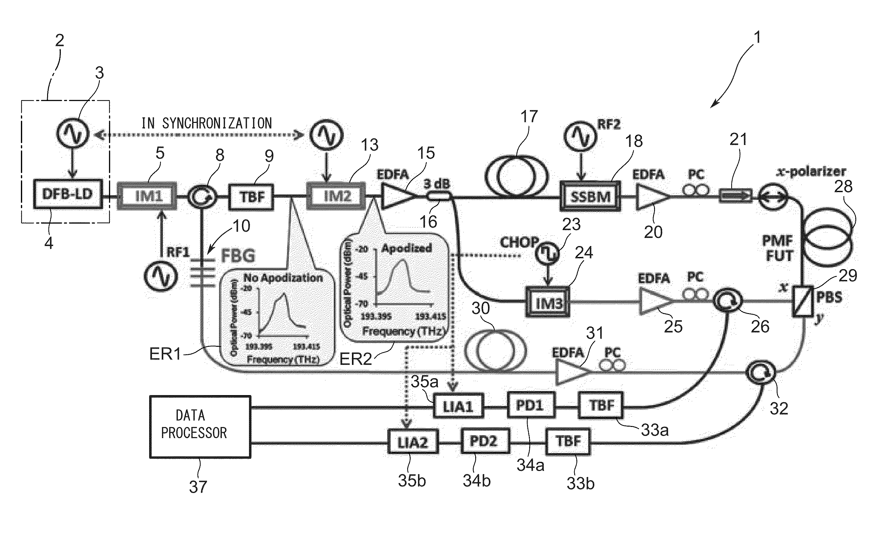
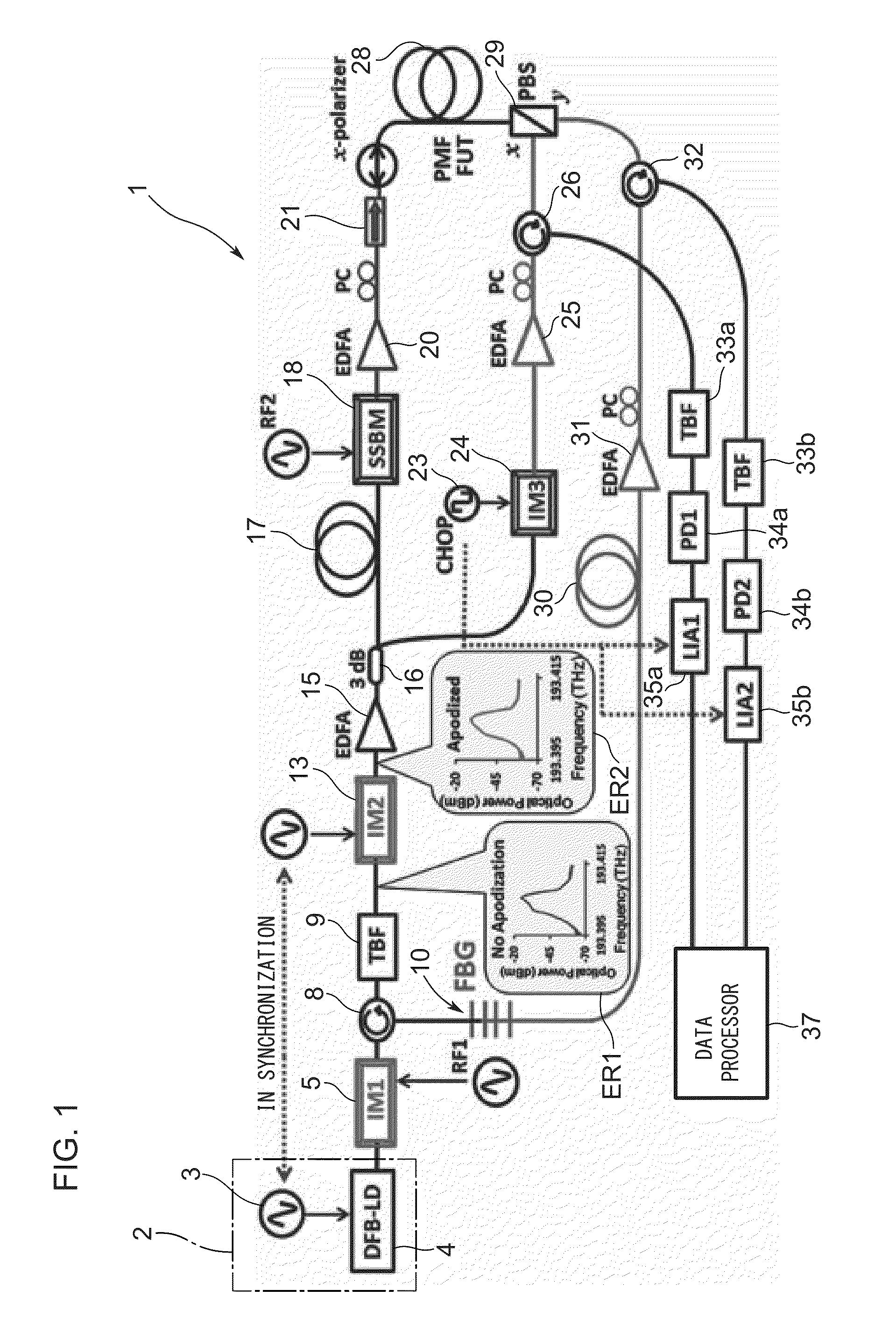
[0025]FIG. 1 illustrates an optical fiber property measuring device 1 according to the present invention, which includes an optical fiber under test 28 constituted of a polarization maintaining fiber (PMF). Here, reference numeral 2 designates a light source constituted of a signal generator 3 and a semiconductor laser 4. As the semiconductor laser 4, a small-size distributed feedback laser diode (DFB-LD) is used which emits laser light of a narrow spectral bandwidth, for example. The signal generator 3 outputs a desired modulation signal into the semiconductor laser 4 as an injection current in order to repeatedly perform frequency modulation (including phase modulation) of continuous laser light emitted from the semiconductor laser 4 in a sinusoidal shape.

[0026]Reference numeral 5 designates an optical intensity modulator (IM1) that modulates the intensity of light output from the semiconductor laser 4 to generate, for example, laser light having a frequency component of ±two doze...

second embodiment

[0067]FIG. 8 illustrates an optical fiber property measuring device 41 in the present invention. In FIG. 8, an optical filter 42 having an appropriate transmission spectral characteristic is arranged in place of the optical intensity modulator 13 in the probe light / pump light generating optical path for output light from the light source 2. In this case, the optical filter 42 as an intensity modulation means substantially performs intensity modulation in synchronization with the frequency modulation of the output light from the light source 2, so that the spectrum distribution of the output light can appropriately be adjusted. When the optical filter 42 is used, the filtering characteristic of the optical filter 42 itself enables the intensity of output light to be adjusted in accordance with the frequency of the output light. This makes it extremely easy to suppress the Brillouin dynamic grating generated at the position other than the correlation peak without the necessity of a sy...

third embodiment

[0070]Contrary to this, when the frequency of the output light of the light source 46 is changed with the triangular waveform illustrated in FIG. 10C, the waveform stays in each frequency for the same time period. As a result, a uniform spectrum intensity is obtained as illustrated in FIG. 10D. In the third embodiment, the above-stated intensity modulation means is constituted of a signal generator 47 that modulates the frequency of the light output from the light source 46 with a repetitive waveform other than the sinusoidal waveform. The intensity modulation applied to the output light is implemented by the signal generator 47 that modulates the frequency of the light output from the light source 46 with a repetitive waveform other than the sinusoidal waveform. Thus, the frequency modulation waveform of output light is changed into a waveform other than the sinusoidal wave shape using the signal generator 47. This simple operation makes it extremely easy to suppress the Brillouin ...


PUM


Abstract

There are proposed an optical fiber property measuring device and an optical fiber property measuring method which can enhance spatial resolution more than before. In the present invention, in synchronization with frequency modulation applied to x-polarized light, intensity modulation is also applied to the x-polarized light by an intensity modulation means. This makes it possible to increase or decrease the intensity of the x-polarized light at a specific frequency, thereby allowing the effective length of a Brillouin dynamic grating formed by the x-polarized light to be adjusted. As a result, the shape of the reflection spectrum obtained when y-polarized light is reflecting by the Brillouin dynamic grating can also be adjusted optimally, which leads to enhancement of spatial resolution with the y-polarized light.

Description

TECHNICAL FIELD[0001]The present invention relates to an optical fiber property measuring device and an optical fiber property measuring method. The present invention more particularly relates to an optical fiber property measuring device and an optical fiber property measuring method for sensing distribution of strain and temperature applied to a polarization maintaining-type optical fiber under test as a measurement target by using a stimulated Brillouin scattering phenomenon and a Brillouin dynamic grating phenomenon generated in this optical fiber under test.BACKGROUND ART[0002]Brillouin scattering in an optical fiber is changed depending on a strain applied to the optical fiber. There has conventionally been devised a technique for measuring distributed strain along the optical fiber by using this phenomenon. This measuring technique enables the level of strain to be measured by measurement of a frequency change in Brillouin scattered light, and also enables distorted part of t...

Claims


Application Information

Patent Timeline
IPC IPC(8): G01M11/00
CPCG01M11/39G01M11/3181G01D5/35364
Inventor HOTATE, KAZUOYAMASHITA, RODRIGO K.HE, ZUYUAN
Owner THE UNIV OF TOKYO
Why Eureka
Try Eureka