Conductive film and touch panel

a technology of touch panel and conductive film, which is applied in the field of conductive film, can solve the problems of reducing detection accuracy, reducing visibility, and limitation in improving detection accuracy, so as to improve detection accuracy, improve detection accuracy, and improve visibility

Active Publication Date: 2016-09-22
FUJIFILM CORP
View PDF0 Cites 30 Cited by
  • Summary
  • Abstract
  • Description
  • Claims
  • Application Information

AI Technical Summary

Benefits of technology

[0008]In contrast, a structure will be considered in which a plurality of grids formed by thin wires made of metal (thin metal wires) are arranged to form an electrode, thereby reducing surface electrical resistance, as in JP2012-238278A, JP2012-043652A, JP2010-191504A, and JP2010-541109A.
[0029]As described above, according to the conductive film and the touch panel of the invention, since the extraction electrode which is formed in a visible region is less likely to be seen, it is possible improve visibility. In addition, since the initial capacitance between the electrodes is high, it is possible to improve the accuracy of detection. The electrodes can be formed on only one main surface of the base. Therefore, it is possible to reduce costs.

Problems solved by technology

Since the extraction electrode is formed in a visible region, there is a problem that the extraction electrode is conspicuous, which results in a reduction in visibility.
Therefore, the initial capacitance between the electrodes is significantly less than that in a transparent electrode film and there is a limitation in improving the accuracy of detection.
When the initial capacitance is too large, a change in capacitance due to the approach or touch of a finger of a human is relatively small and the accuracy of detection is reduced.

Method used


Image

  • Conductive film and touch panel
  • Conductive film and touch panel
  • Conductive film and touch panel

Examples


example 1

[0095](Photosensitive Silver Halide Material)

[0096]An emulsion was prepared which contained silver iodobromochloride particles having a sphere-equivalent average diameter of 0.1 μm (I=0.2% by mol, Br=40% by mol) dispersed in an aqueous medium containing 10.0 g of gelatin per 150 g of Ag.

[0097]In addition, K3Rh2Br9 and K2IrCl6 were added to the emulsion at a concentration of 10−7 (mol / mol-Ag) to dope the silver bromide particles with Rh ions and Ir ions. Na2PdCl4 was added to the emulsion and the resultant emulsion was subjected to gold-sulfur sensitization, using chlorauric acid and sodium thiosulfate. Then, the emulsion was used as an emulsion A. Then, the amount of K3Rh2Br9 in the emulsion A was reduced to prepare an emulsion of which the sensitivity was doubled. The emulsion was used as an emulsion B.

[0098](Formation of Photosensitive Layer)

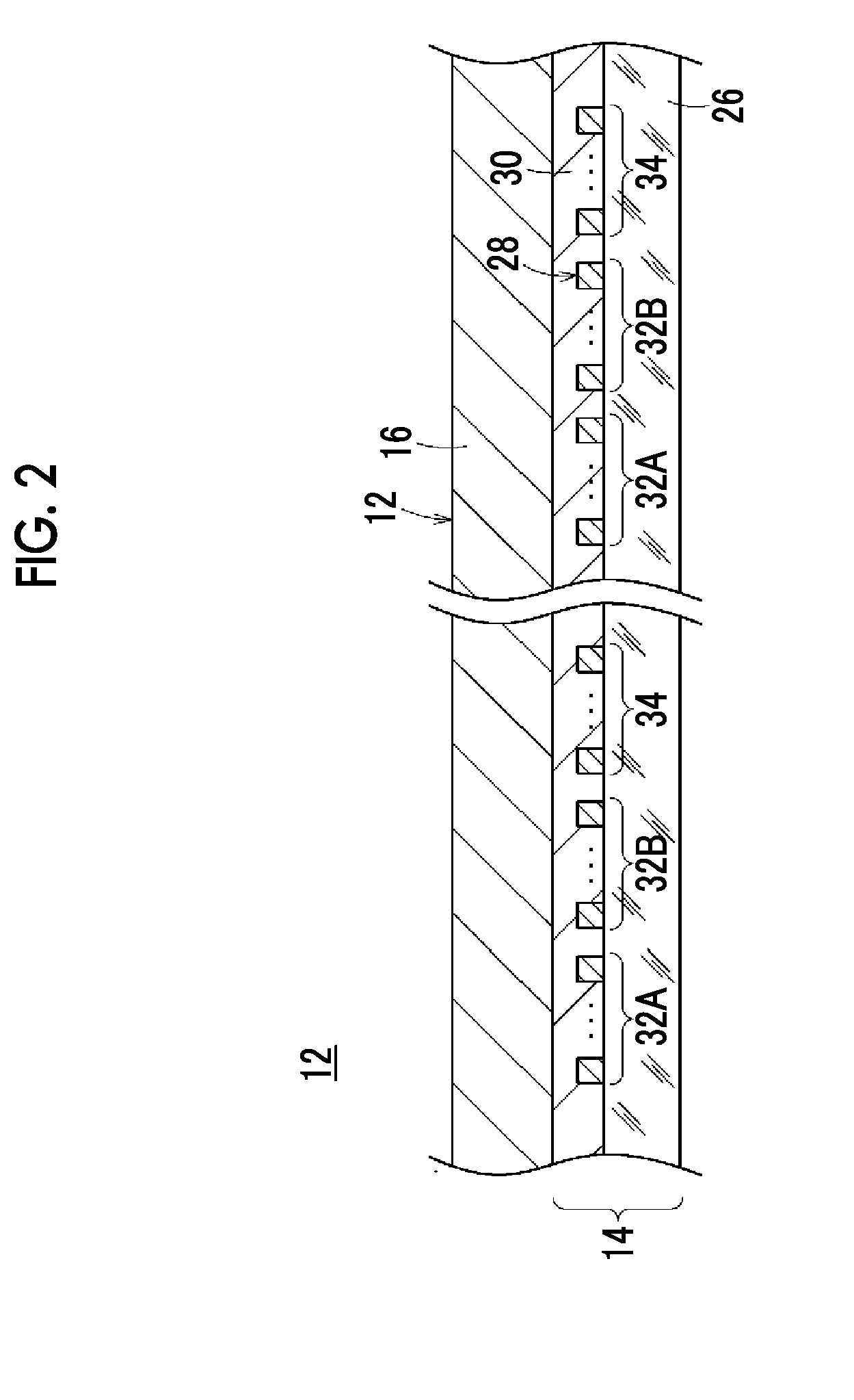
[0099]Then, the emulsion and a gelatin hardening agent were applied onto the surface of the transparent base 26 (which was made of PET in thi...

example 2

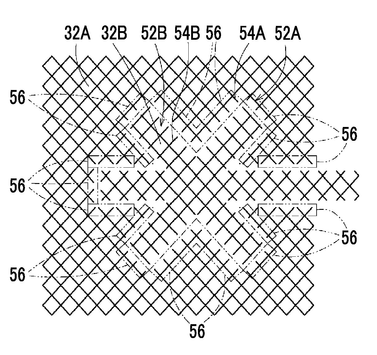
[0108]A conductive film according to Example 2 was obtained by the same method as that in Example 1 except that the first electrode 32A and the second electrode 32B were formed in the pattern illustrated in FIGS. 6A and 6B, instead of the pattern illustrated in FIG. 3. In Example 2, the total length L of the path / the area A was 0.9 (mm−1).

example 3

[0109]A conductive film according to Example 3 was obtained by the same method as that in Example 1 except that the first electrode 32A and the second electrode 32B were formed in the pattern illustrated in FIGS. 7A and 7B, instead of the pattern illustrated in FIG. 3. In Example 3, the total length L of the path / the area A was 1.0 (mm−1).


PUM


Abstract

Provided are a conductive film and a touch panel in which an extraction electrode that is formed in a visible region is inconspicuous to improve visibility, the initial capacitance between electrodes is increased to improve the accuracy of detection, and the electrodes are formed on only one main surface of a base to reduce costs. The conductive film includes a transparent base, first and second electrodes 32A and 32B that are formed on a main surface of the transparent base so as to face each other, and an extraction electrode 34 that is formed on the main surface of the transparent base and extends from the second electrode 32B. The first electrode 32A has a shape which surrounds a portion of the second electrode 32B. At least the extraction electrode 34 is formed in a mesh pattern 38 including a plurality of grids 36 which are formed by thin metal wires.

Description

CROSS-REFERENCE TO RELATED APPLICATIONS[0001]This application is a Continuation of PCT International Application No. PCT / JP2014 / 077300 filed on Oct. 14, 2014, which claims priority under 35 U.S.C §119(a) to Japanese Patent Application No. 2013-247282 filed Nov. 29, 2013. Each of the above applications is hereby expressly incorporated by reference, in its entirety, into the present application.BACKGROUND OF THE INVENTION[0002]1. Field of the Invention[0003]The present invention relates to a conductive film, and more particularly, to a conductive film suitable for a touch panel and a touch panel.[0004]2. Description of the Related Art[0005]In recent years, a conductive film which is used in a touch panel has drawn attention as a conductive film provided in a display device. This touch panel is mainly applied to a small device, such as a PDA (portable information terminal) or a mobile phone. Increasing the size of the touch panel may be considered for application to, for example, perso...

Claims


Application Information

Patent Timeline
Patent Type & Authority Applications(United States)
IPC IPC(8): G06F3/041G06F3/044
CPCG06F3/0416G06F3/044G06F2203/04112G06F2203/04103G06F3/0412G06F3/0443G06F3/0448G06F3/0446
Inventor NAKAMURA, HIROSHIGE
Owner FUJIFILM CORP
Why Eureka
Try Eureka