Target for magnetron sputtering

a magnetron sputtering and target technology, applied in the direction of electrical apparatus, basic electric elements, metal material coating process, etc., can solve the problems of inefficiency of sputtering, achieve stable voltage, no risk of composition change, and high pass-through-flux

Inactive Publication Date: 2016-09-22
TANAKA PRECIOUS METAL IND
View PDF7 Cites 12 Cited by
  • Summary
  • Abstract
  • Description
  • Claims
  • Application Information

AI Technical Summary

Benefits of technology

[0019]The nonmagnetic metal powder may include at least one element selected from a group consisting of B, Ti, V, Mn, Zr, Nb, Ru, Mo, Ta, W. The oxide powder may include an oxide of at least one element selected from the group consisting of Si, Ti, Ta, Cr, Co, B, Fe, Cu, Y, Mg, Al, Zr, Nb, Mo, Ce, Sm, Gd, W, Hf, Ni or a composite oxide thereof. The magnetic metal powder may be formulated as an alloy. And, the nonmagnetic metal powder and the magnetic metal p

Problems solved by technology

The target for magnetic recording medium used in magnetron sputtering is faced with a dilemma in which it is required to include a ferromagnetic metal element so as to produce a magnetic recording medium having a magneti

Method used


Image

  • Target for magnetron sputtering
  • Target for magnetron sputtering
  • Target for magnetron sputtering

Examples


example 1

[0068]The composition of the entire target prepared as Example 1 was 90 (71 Co-10 Cr-14 Pt-5 Ru)-7 SiO2-3 Cr2O3. The compositional ratios of elements below all take the unit of atomic %.

[0069]The metals were measured off so that the alloy composition amounts to 46.829 Co-20.072 Cr-23.063 Pt-10.036 Ru (the proportion of Co and Cr are 70 atomic % of Co and 30 atomic % of Cr), and the alloy was heated to 1550° C. to melt the metals and form molten metal, to prepare a Co—Cr—Pt—Ru powder by gas atomization at a spraying temperature of 1750° C.

[0070]Then, the metals were measured off to form an alloy composition of 95 Co-5 Pt, the alloy was heated to 1500° C. to melt the metals and form molten metal to prepare a Co—Pt powder by gas atomization at a spraying temperature of 1700° C.

[0071]The two types of atomized powders prepared above were classified by sieves to obtain a Co—Cr—Pt—Ru powder of a particle size of 10 μm to 100 μm and a Co—Pt powder of a particle size of 10 μm to 100 μm.

[0072...

example 2

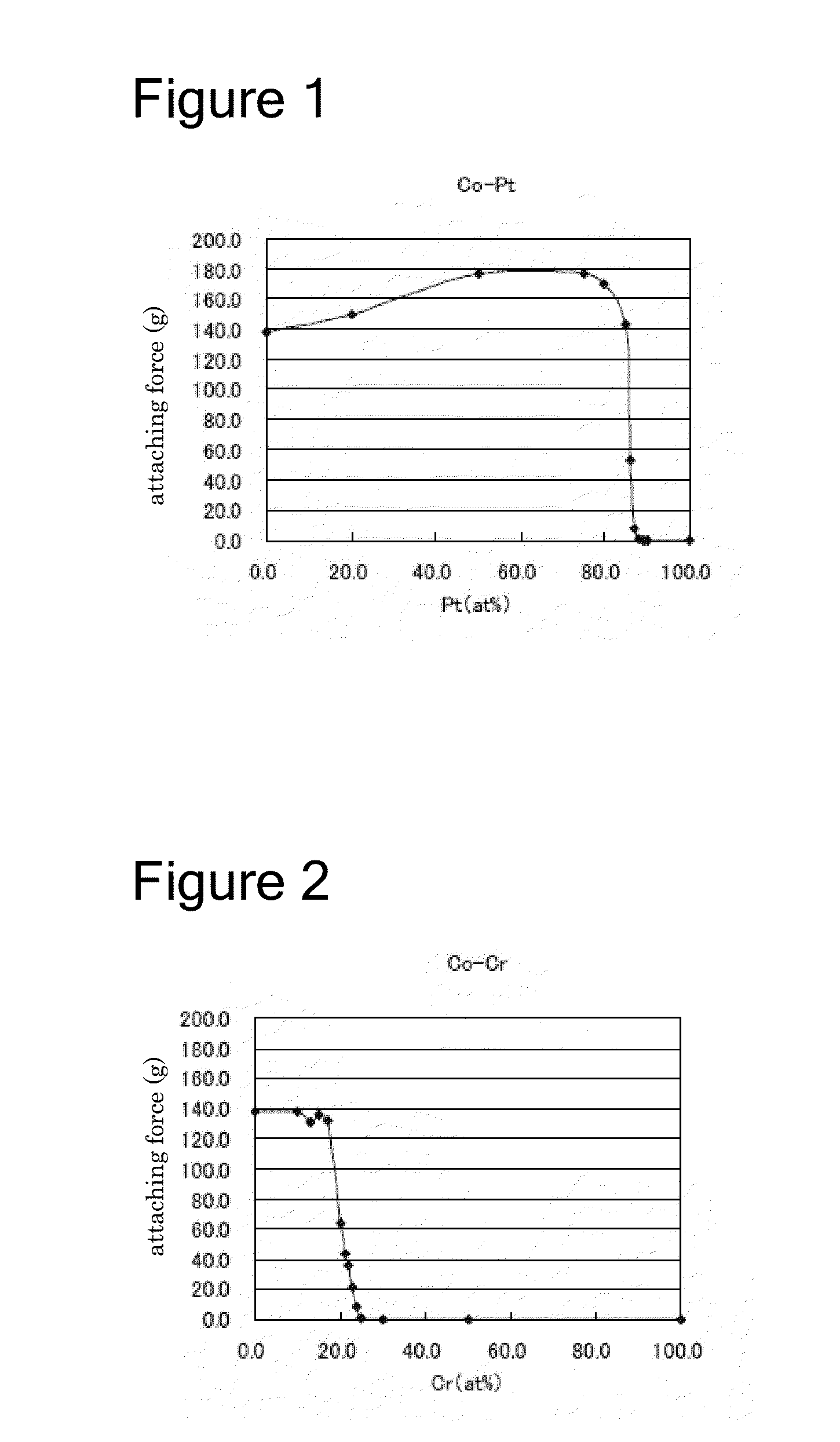
[0110]The rate of Pt in the Co—Pt phase was altered in the range of 4 atomic % to 10 atomic %, and (2) the rate of Cr (Cr / (Cr+Co)) in the Co—Cr—Pt phase was altered in the range of 30 atomic % to 95 atomic % of Cr, and SiO2, TiO2 and Co3O4 were used as oxides to manufacture the sintered object (Co—Cr—Pt—Ru—SiO2—TiO2—Co3O4) by a similar process as Example 1 to assess the pass-through-flux (PTF). The content ratio (volume %) of the materials of each sintered object and the pass-through-flux (PTF) are shown in Table 3.

TABLE 3First Powder MixtureCo—PtFirst PowderCo—PtCo—Cr—Pt phase (vol %)Oxide phase (vol %)phaseMixtureMixtureNo.Or / (Oo + Or)CoCrPtRuSiO2TiO2Co3O4SUMPt (at %)(vol %)(vol %)PTF (%)13028.11%13.10%15.50%7.40%11.05%8.04%16.81%100.00%477.55%22.45%59.623028.23%13.15%15.15%7.43%11.09%8.07%16.88%100.00%576.98%23.02%60.133028.35%13.21%14.79%7.46%11.14%8.10%16.95%100.00%676.40%23.60%60.643028.47%13.27%14.42%7.49%11.19%8.14%17.02%100.00%775.80%24.20%61.053028.60%13.32%14.04%7.53%11.2...


PUM

PropertyMeasurementUnit
Percent by atomaaaaaaaaaa

Abstract

The invention provides a new sputtering target that provides a large leakage of magnetic flux, is free of the risk of a change of composition during deposition, and enables deposition under a stable voltage.
A sputtering target is that having (1) a Co—Pt magnetic phase including Co and Pt, wherein Pt is included at a proportion of 4 atomic % to 10 atomic %; (2) a Co—Cr—Pt nonmagnetic phase including Co, Cr and Pt, wherein Co and Cr are included at proportions of 30 atomic % or more of Cr and 70 atomic % or less of Co; and (3) an oxide phase including finely dispersed metal oxides.

Description

TECHNICAL FIELD[0001]The present invention relates to a target for magnetron sputtering for use in manufacture of a magnetic recording medium and a manufacture process of the same.BACKGROUND ART[0002]Generally, when manufacturing computer hard disks and other magnetic recording media, the magnetron sputtering method is used to deposit magnetic thin films that retain magnetic records. Sputtering is a technique of ejecting atoms by bombarding a target surface with plasma occurring from ionization of gas introduced into a vacuum space and depositing those atoms to a substrate surface.[0003]Magnetron sputtering is a method of performing sputtering by placing magnets on back of the target so that magnetic flux would leak out to the target surface, i.e., pass-through flux (PTF), thereby inducing concentration of plasma around the target. This method improves the deposition efficiency as well as prevents plasma from damaging the substrate.[0004]A problem encountered when depositing magneti...

Claims


Application Information

Patent Timeline
IPC IPC(8): H01J37/34C23C14/10C23C14/14B22F9/04C23C14/35C22C19/07B22F3/10B22F1/00C23C14/08C23C14/34
CPCH01J37/3429C23C14/083C23C14/10C23C14/14C23C14/3414C23C14/35B22F2302/25B22F3/10B22F1/0003B22F9/04B22F2009/045B22F2301/15B22F2302/256C22C19/07G11B5/851C22C1/0433C22C1/045C22C32/0026B22F1/09
Inventor GOTO, YASUYUKIKOBAYASHI, YUSUKEWATANABE, YASUNOBU
Owner TANAKA PRECIOUS METAL IND
Why Eureka
Try Eureka