Filter component

a filter component and filter technology, applied in the field of filter components, can solve the problems of insufficient attenuation of common mode noise and deterioration of attenuation characteristics of attenuating common mode noise of lc series resonance circuit, and achieve the effect of effectively attenuating common mode noise, widening the frequency range of attenuation characteristics, and less sharp resonance characteristics

Active Publication Date: 2016-09-22
MURATA MFG CO LTD
View PDF5 Cites 10 Cited by
  • Summary
  • Abstract
  • Description
  • Claims
  • Application Information

AI Technical Summary

Benefits of technology

[0029]By setting the parasitic resistance of the first inductor of the first LC series resonance circuit and the second inductor of the second LC series resonance circuit to be greater in this manner, the Q factor of each of the first and second LC series resonance circuits is decreased, thus making the resonance characteristics less sharp. It is thus possible to widen the frequency range of the attenuation characteristics for common mode noise near the attenuation poles provided by the first and second LC series resonance circuits.
[0030]According to various preferred embodiments of the present invention, the first LC series resonance circuit disposed in the shunt circuit is connected at one end to the first line and is grounded at the other end, and the second LC series resonance circuit disposed in the shunt circuit is grounded at one end and is connected at the other end to the second line. With this configuration, the first and second LC series resonance circuits resonate reliably so as to provide attenuation poles. Accordingly, the resonant frequency of each of the first and second LC series resonance circuits is set to be a frequency that effectively attenuates common mode noise, thus making it possible to reliably attenuate common mode noise. It is thus possible to provide a filter component in which the attenuation characteristics for common mode noise are improved.

Problems solved by technology

In this case, the inductor Lc connected to the node T which is grounded virtually does not function sufficiently, and thus, the attenuation characteristics for attenuating common mode noise exhibited by the LC series resonance circuit may be deteriorated.
Additionally, since the LC series resonance circuit is formed by the inductor Lc connected to the virtually grounded node T, if the node T is formed at a position displaced from the ideal virtual ground point due to the restrictions of the structure of the filter component 500, the following problem may occur.
A phase shift occurs in the common mode noise, and thus, common mode noise may not be sufficiently attenuated.

Method used


Image

  • Filter component
  • Filter component
  • Filter component

Examples


first preferred embodiment

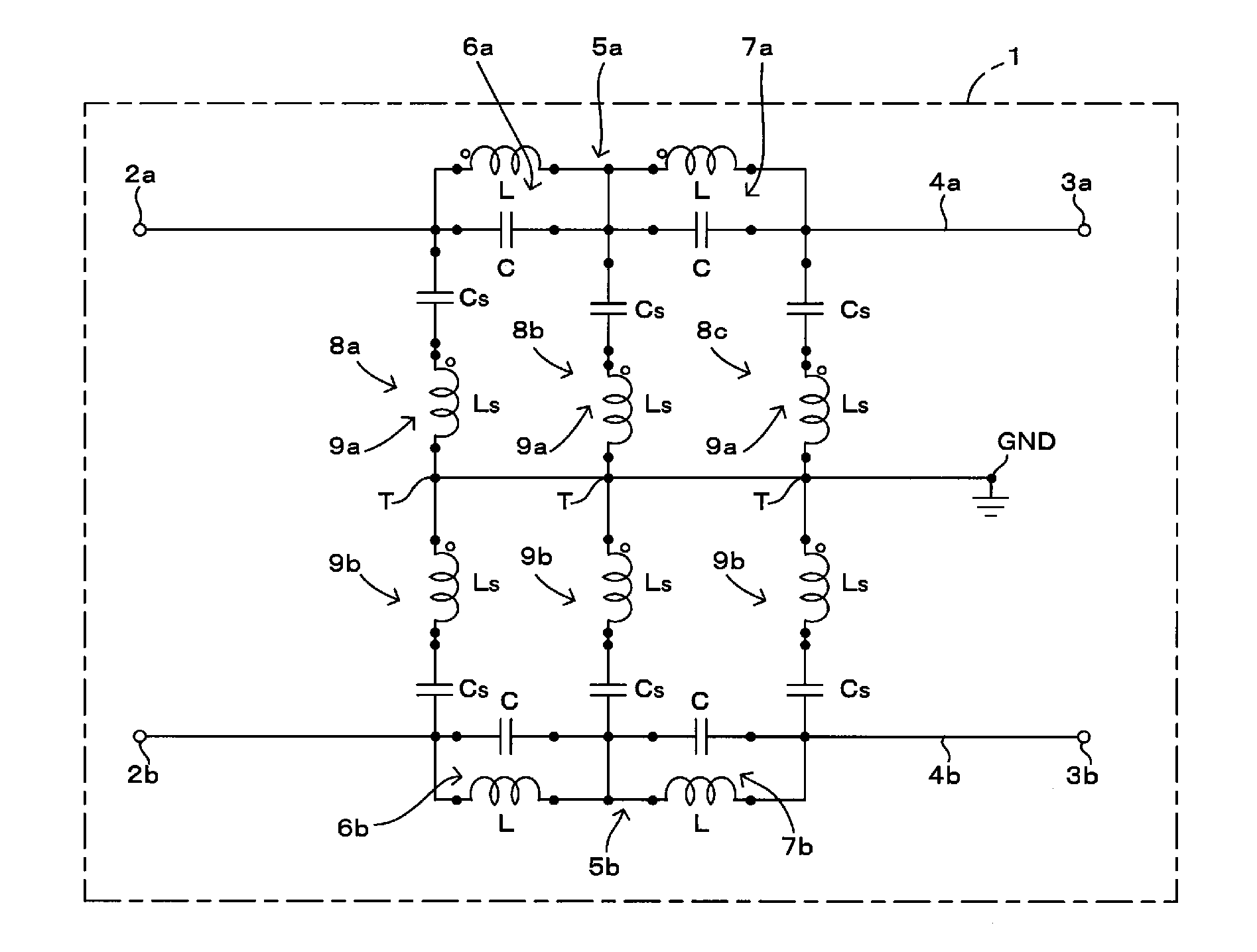
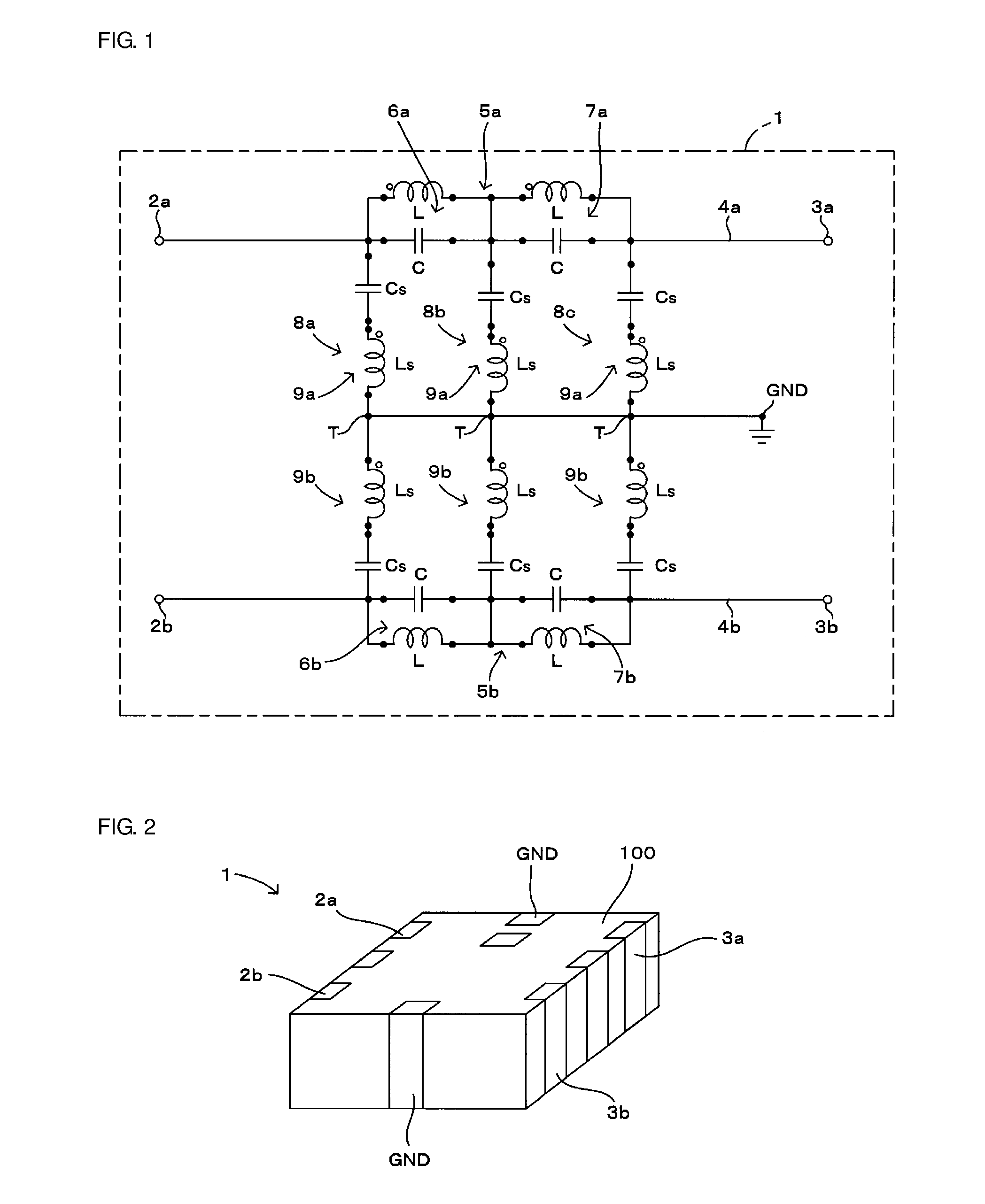
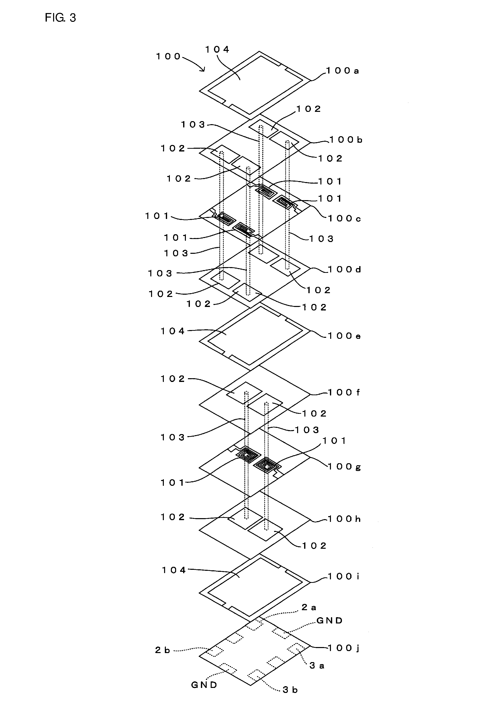
[0051]A first preferred embodiment of the present invention will be described below with reference to FIGS. 1 through 4. FIG. 1 is a circuit diagram of a filter component according to the first preferred embodiment of the present invention. FIG. 2 is an external view of the filter component shown in FIG. 1. FIG. 3 is an enlarged view of the major portion of the internal portion of the filter component shown in FIG. 2. FIG. 4 is a graph illustrating frequency characteristics of the filter component shown in FIG. 1. In FIG. 3, among layers of a multilayer substrate included in the filter component shown in FIG. 2, only the lower layers of the multilayer substrate in which shunt circuits 8a, 8b, and 8c are disposed are shown.

[0052]An overview of the circuit configuration of a filter component 1 will be described below.

[0053]The filter component 1 shown in FIG. 1 has a function of eliminating common mode noise which propagates through differential lines. The filter component 1 includes ...

second preferred embodiment

[0077]A second preferred embodiment of the present invention will be described below with reference to FIGS. 7 and 8. FIG. 7 is a circuit diagram of a filter component according to the second preferred embodiment of the present invention. FIG. 8 is a graph illustrating frequency characteristics of the filter component shown in FIG. 7.

[0078]A filter component 1a of this preferred embodiment differs from the filter component 1 shown in FIG. 1 in the following points. As shown in FIG. 7, a shunt circuit 8 which connects the first line 4a and the second line 4b with each other is disposed only between the node between the LC parallel resonance circuits 6a and 7a on the first line 4a and the node between the LC parallel resonance circuits 6b and 7b on the second line 4b. The node T between the LC series resonance circuits 9a and 9b of the shunt circuit 8 is grounded via an inductor Lg (corresponding to “a third inductor”). The configurations of the other elements are similar to those of ...

third preferred embodiment

[0088]A third preferred embodiment of the present invention will be described below with reference to FIGS. 13 and 14. FIG. 13 is a circuit diagram of a filter component according to the third preferred embodiment of the present invention. FIG. 14 is a graph illustrating frequency characteristics of the filter component shown in FIG. 13.

[0089]A filter component 1b of this preferred embodiment differs from the filter component 1a shown in FIG. 7 in the following points. As shown in FIG. 13, in the first filter circuit 5a, a BEF is defined by a single LC parallel resonance circuit 6a, and in the second filter circuit 5b, a BEF is defined by a single LC parallel resonance circuit 6b. The shunt circuit 8 which connects the first line 4a and the second line 4b with each other is located between the previous stage of the LC parallel resonance circuit 6a and the previous stage of the LC parallel resonance circuit 6b. The configurations of the other elements are similar to those of the abov...


PUM


Abstract

In a filter component with improved attenuation characteristics for common mode noise, an LC series resonance circuit disposed in each of a plurality of shunt circuits is connected at a first end to a first line and is grounded at a second end. The LC series resonance circuit disposed in each of the shunt circuits is grounded at a first end and is connected at a second end to a second line. With this configuration, the LC series resonance circuits resonate reliably so as to define attenuation poles. Accordingly, the resonant frequency of each of the LC series resonance circuits is set to be a frequency that effectively attenuates common mode noise.

Description

BACKGROUND OF THE INVENTION[0001]1. Field of the Invention[0002]The present invention relates to a filter component that eliminates common mode noise which propagates through differential lines, and more particularly, to a technology that improves attenuation characteristics of the filter component.[0003]2. Description of the Related Art[0004]A known filter component includes a filter circuit for eliminating common mode noise which propagates through differential lines. As shown in the circuit diagram in FIG. 19, in a known filter component 500, passive series elements 504a and 504b are respectively connected in series with first and second lines 503a and 503b disposed between first and second differential input terminals 501a and 501b and first and second differential output terminals 502a and 502b, respectively, and a passive parallel element 505 is connected in parallel between the first and second lines 503a and 503b, thus forming a ladder differential four-terminal circuit.[000...

Claims


Application Information

Patent Timeline
Patent Type & Authority Applications(United States)
IPC IPC(8): H03H7/01H03H7/42H03H7/075
CPCH03H7/0115H03H7/427H03H7/075H03H2001/0085H03H7/1758H03H7/1766H03H2007/013
Inventor TERAMOTO, MASAHIRO
Owner MURATA MFG CO LTD
Why Eureka
Try Eureka