Discharge System

a discharge system and discharge device technology, applied in mechanical devices, couplings, coatings, etc., can solve problems such as poor connection between discharge devices

Active Publication Date: 2016-09-29
HEISHIN ENGINEERING & EQUIPMENT CO LTD
View PDF7 Cites 3 Cited by
  • Summary
  • Abstract
  • Description
  • Claims
  • Application Information

AI Technical Summary

Benefits of technology

[0010]According to such a configuration, the discharge-side coupler can be connected to the refill-side coupler so as to substantially be aligned with each other. Therefore, a poor connection of the discharge-side coupler to the refill-side coupler can be prevented. Further, problems such as leaks of the fluid during the refilling operation, and wear of the refill-side coupler and the discharge-side coupler associated with sliding of the couplers can be solved.
[0012]In the discharge system of the present invention, the coupling position between the manipulator and the discharging device comes to a position on the axial line when connecting the discharge-side coupler to the refill-side coupler. Thus, when connecting the discharge-side coupler to the refill-side coupler, the external force acts in the axial line direction on the axial line and the discharge-side coupler can be connected to the refill-side coupler so as to substantially be aligned with each other. Therefore, according to the present invention, the poor connection of the discharge-side coupler to the refill-side coupler can be prevented and problems such as the leaks of the fluid and the wear of each coupler can be solved.
[0015]According to such a configuration, the discharging device is held so as not to separate from the refilling device during the refilling operation of the fluid, and a load associated with the connection of the discharge-side coupler and the refill-side coupler, or the refilling of the fluid can be prevented from acting on the manipulator.
[0017]According to such a configuration, the load associated with the connection of the discharge-side coupler and the refill-side coupler, or the refilling of the fluid can be received properly by the disconnection preventive mechanism.
[0018]According to the embodiments of the present invention, a discharge system can be provided, which adopts an optimal structure for surely connecting a discharging device to a refilling device by moving the discharging device.

Problems solved by technology

However, in the conventional arts, there is no measures against the axial offset and, thus, there is a problem that a poor connection may be caused between the discharging device and the refilling device.

Method used


Image

  • Discharge System
  • Discharge System
  • Discharge System

Examples


Embodiment Construction

Configuration of Discharge System 10

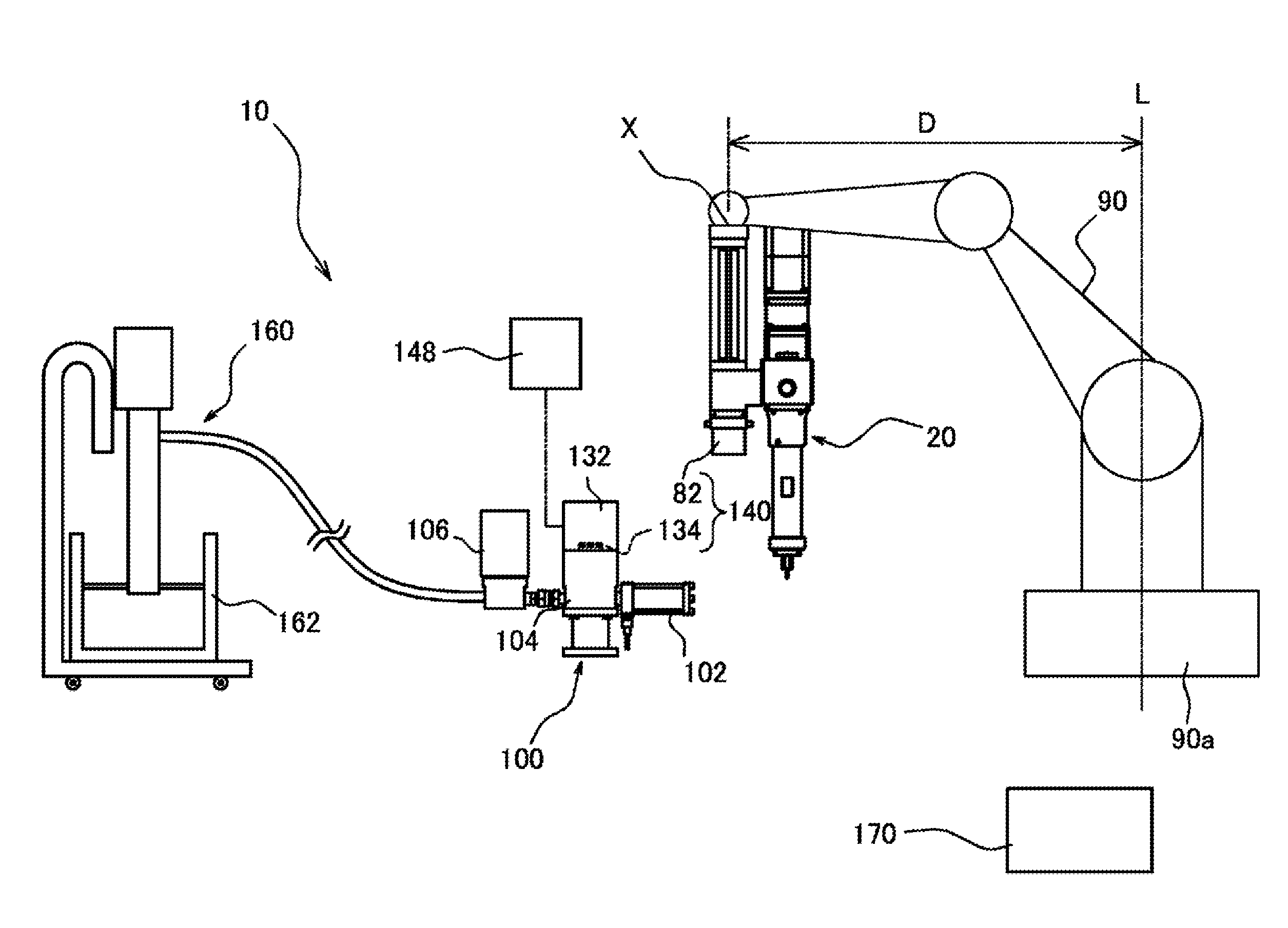
[0035]Hereinafter, a discharge system 10 according to one embodiment of the present invention is described in detail, referring to the accompanying drawings. As illustrated in FIG. 1, the discharge system 10 includes the discharging device 20, the refilling device 100, a fluid feeder 160, and a controller 170, as primary components. The discharge system 10 is capable of refilling the discharging device 20 with fluid which is supplied from the fluid feeder 160, by connecting the discharging device 20 to the refilling device 100. The discharge system 10 is capable of discharging the refilled fluid for an application purpose by being operated in a state where discharging device 20 is disconnected from the refilling device 100. That is, the discharge system 10 has a system configuration which is capable of applying the fluid by actuating the discharging device 20 independently from the refilling device 100 or the fluid feeder 160 in a state where pipi...


PUM


Abstract

The purpose is to provide a discharge system that adopts an optimal structure for connecting a discharging device to a refilling device in a substantially aligned fashion by moving the discharging device. A discharge system includes a discharging device, a refilling device, a discharge-side coupler, a refill-side coupler, and a manipulator. The discharge-side coupler is connectable to the refill-side coupler by relatively moving the discharge-side coupler in an axial line N direction of the refill-side coupler and fluid can be refilled from the refilling device side to the discharging device side. A coupling position between the manipulator and the discharging device reaches on the axial line N when connecting the refill-side coupler and the discharge-side coupler.

Description

[0001]This application is the U.S. National Phase of International Patent Application No. PCT / JP2014 / 076029, filed on Sep. 30 2014, entitled “DISCHARGING SYSTEM,” and claims priority under 35 U.S.C. §119 to Japanese Patent Application No. 2013-224660, filed Oct. 29, 2013 and Japanese Patent Application No. 2014-148658, filed Jul. 22, 2014, which are hereby expressly incorporated by reference in their entirety for all purposes.TECHNICAL FIELD[0002]The present invention relates to a discharge system capable of using fluid, for example, capable of applying fluid, such as sealing agent or adhesive, to various components at an automobile assembly plant etc., or refilling a container with fluid, such as grease.BACKGROUND ART[0003]Conventionally, as listed below, a device and a method for applying a functional fluid material disclosed in Patent Document 1: JP2004-154733A, or a connector for fluid, an application device, etc. which are disclosed in Patent Document 2: JP2007-275769A, are use...

Claims


Application Information

Patent Timeline
Patent Type & Authority Applications(United States)
IPC IPC(8): B05C11/10B05C5/02B05B12/14
CPCB05C11/10B05C5/0216B05B12/14B05B13/0431B05C5/0225B05C11/1047F16L37/34
Inventor TANAKA, YUSUKE
Owner HEISHIN ENGINEERING & EQUIPMENT CO LTD
Why Eureka
Try Eureka