Electrically driven pump

Active Publication Date: 2016-09-29
ZHEJIANG SANHUA AUTOMOTIVE COMPONENTS
View PDF8 Cites 8 Cited by
  • Summary
  • Abstract
  • Description
  • Claims
  • Application Information

AI Technical Summary

Benefits of technology

[0008]Compared with the conventional technology, a cooling passage is provided in the present application, and at least part of the wall of the cooling passage is in direct or indirect contact with the electronic control unit, and the working medium in the cooling passage exchanges heat with the electronic control unit, which facilitates improving the service life of the electronic control

Problems solved by technology

Currently, an electronic control unit of the electrically driven pump generates heat during operation, and in a conventional design, the electronic control unit is away fro

Method used


Image

  • Electrically driven pump
  • Electrically driven pump
  • Electrically driven pump

Examples


first embodiment

[0028]Reference is made to FIG. 6, which is a schematic view showing the structure of the upper surface of the rear housing 3. The rear housing 3 includes a flow guiding groove 362a. The fourth annular protrusion 362 and the flow guiding groove 362a are arranged at interval, and the flow guiding groove 362a is in communication with an area enclosed by an inner side surface of the fourth annular protrusion 362. The fourth annular protrusion 362 further includes a stepped portion 362b, and the height of the stepped portion 362b protruding from the upper surface of the rear housing 3 is lower than the height of the fourth annular protrusion 362 protruding from the upper surface of the rear housing 3. An outer surface of the second bearing 82 is configured to form a tight fit with the inner side surface of the fourth annular protrusion 362, an end surface of the second bearing 82 is configured to abut against an upper surface of the stepped portion 362b, and an inner surface of the seco...

second embodiment

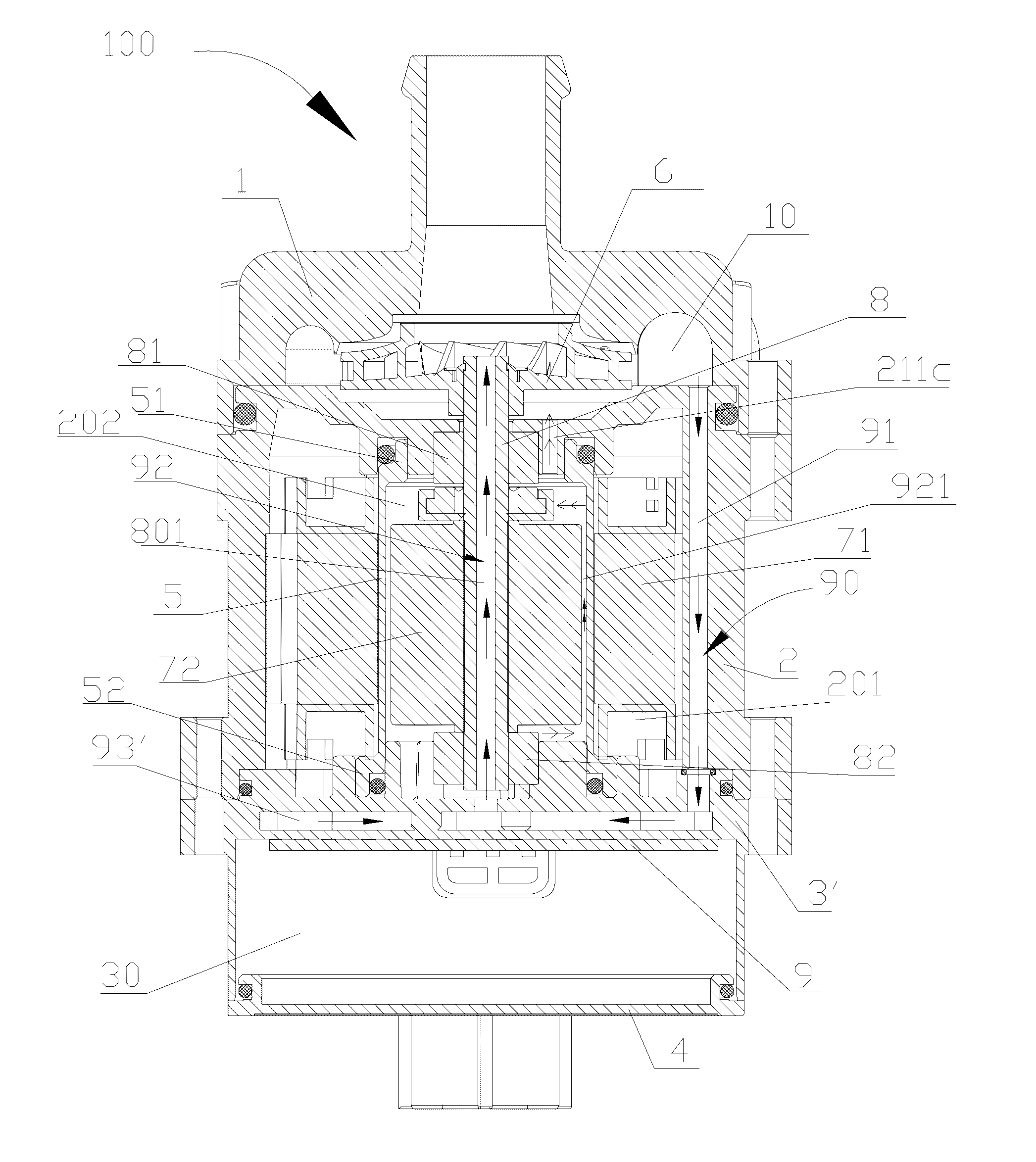
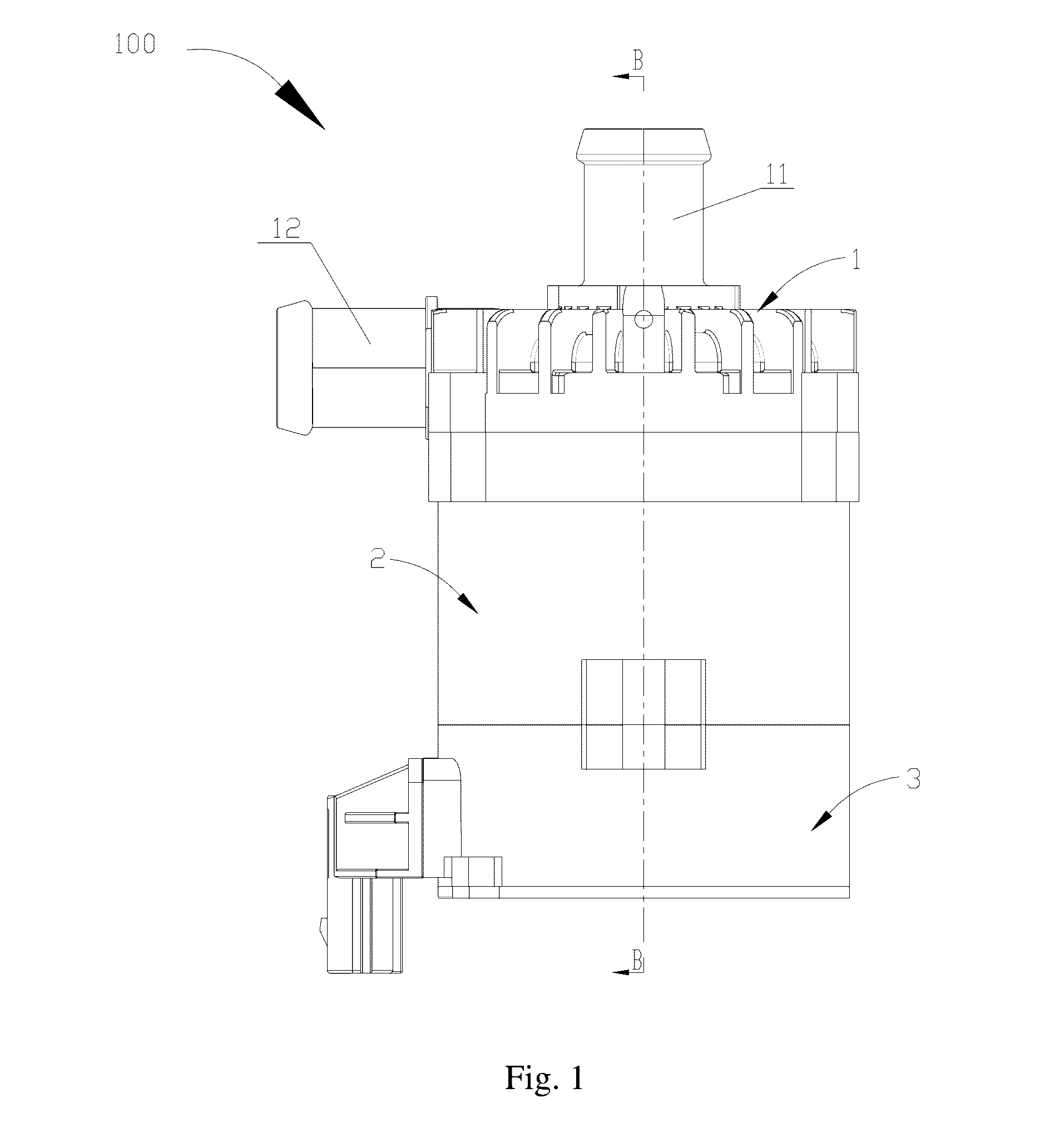
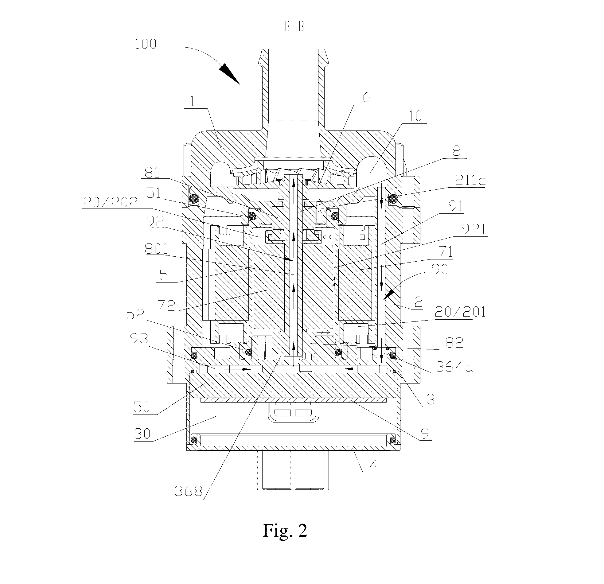
[0037]FIG. 10 is a schematic sectional view of the electrically driven pump 100 in FIG. 1 taken along line B-B. The electrically driven pump 100 includes a first housing 1, a second housing 2, a rear housing 3′, an end cover 4, a partition 5, an impeller 6, a stator 71, a rotor 72, a shaft 8, and an electronic control unit 9. The first housing 1 and the second housing 2 are fixedly connected in a detachable manner and form a relatively sealed structure by arranging a sealing ring at a portion where the first housing 1 and the second housing 2 are connected, and in this embodiment, the first housing 1 and the second housing 2 are connected by a bolt or a screw. An impeller chamber 10 includes a space defined by the first housing 1 and the second housing 2 after being fixed to each other. The impeller 6 is arranged in the impeller chamber 10. The second housing 2 and the rear housing 3′ are threadedly connected, for example, via a bolt, and form the relatively sealed structure through...


PUM


Abstract

An electrically driven pump includes a first housing and a second housing, and the first housing and the second housing are fixed to form an impeller chamber for receiving an impeller. The second housing and a rear housing are fixed to form a first receiving chamber for receiving a motor assembly; and the motor assembly includes a stator and a rotor, the rotor is arranged in an inner cavity enclosed by the stator, and the rotor drives the impeller to rotate. An electronic control unit is cooperated with the motor assembly, and the electronic control unit controls the operation of the motor assembly. The electrically driven pump includes a cooling passage for accommodating a working medium, and the working medium in the cooling passage may exchange heat with the electronic control unit, thereby facilitating improving the service life of the electrically driven pump.

Description

CROSS REFERENCE TO RELATED APPLICATION[0001]This application claims the benefit of priority to Chinese Patent Application No. 201510136356.2 titled “ELECTRICALLY DRIVEN PUMP”, filed with the Chinese State Intellectual Property Office on Mar. 26, 2015, the entire disclosure of which is incorporated herein by reference.FIELD[0002]This application relates to a centrifugal pump, and relates to an electrically driven pump.BACKGROUND[0003]In recent decades, automotive industry develops rapidly, and with the development of the automobile towards a direction of safer, more reliable, more stable, fully automatic intellectualization, environment-protecting and energy-saving, electrically driven pumps have gradually replaced conventional mechanical pumps, and have been widely used in vehicle heat dissipating circulating system. The electrically driven pumps have advantages, such as no electromagnetic interference, high efficiency, environmental protection, stepless speed regulation, and can me...

Claims


Application Information

Patent Timeline
IPC IPC(8): F04D13/06F04D1/00F04D29/42F04D29/58
CPCF04D13/0693F04D29/588F04D29/426F04D1/00F04D29/5813F04D29/5893F04D13/0646F04D29/5806
Inventor ZHANG, RONGRONGBAO, JUNFENGSHI, CHULIANGSONG, HONGMINZHANG, JUNCHAOZHANG, JUN
Owner ZHEJIANG SANHUA AUTOMOTIVE COMPONENTS
Why Eureka
Try Eureka