
Subscriber station for a bus system and method for reducing line-conducted emissions in a bus system

a bus system and subscriber station technology, applied in the direction of instruments, data switching networks, liquid/fluent solid measurement, etc., can solve the problems of switching edges and subject to aging, and achieve the effect of reducing the radiated interferen

Active Publication Date: 2016-09-29
ROBERT BOSCH GMBH
View PDF4 Cites 3 Cited by
  • Summary
  • Abstract
  • Description
  • Claims
  • Application Information

AI Technical Summary

Benefits of technology

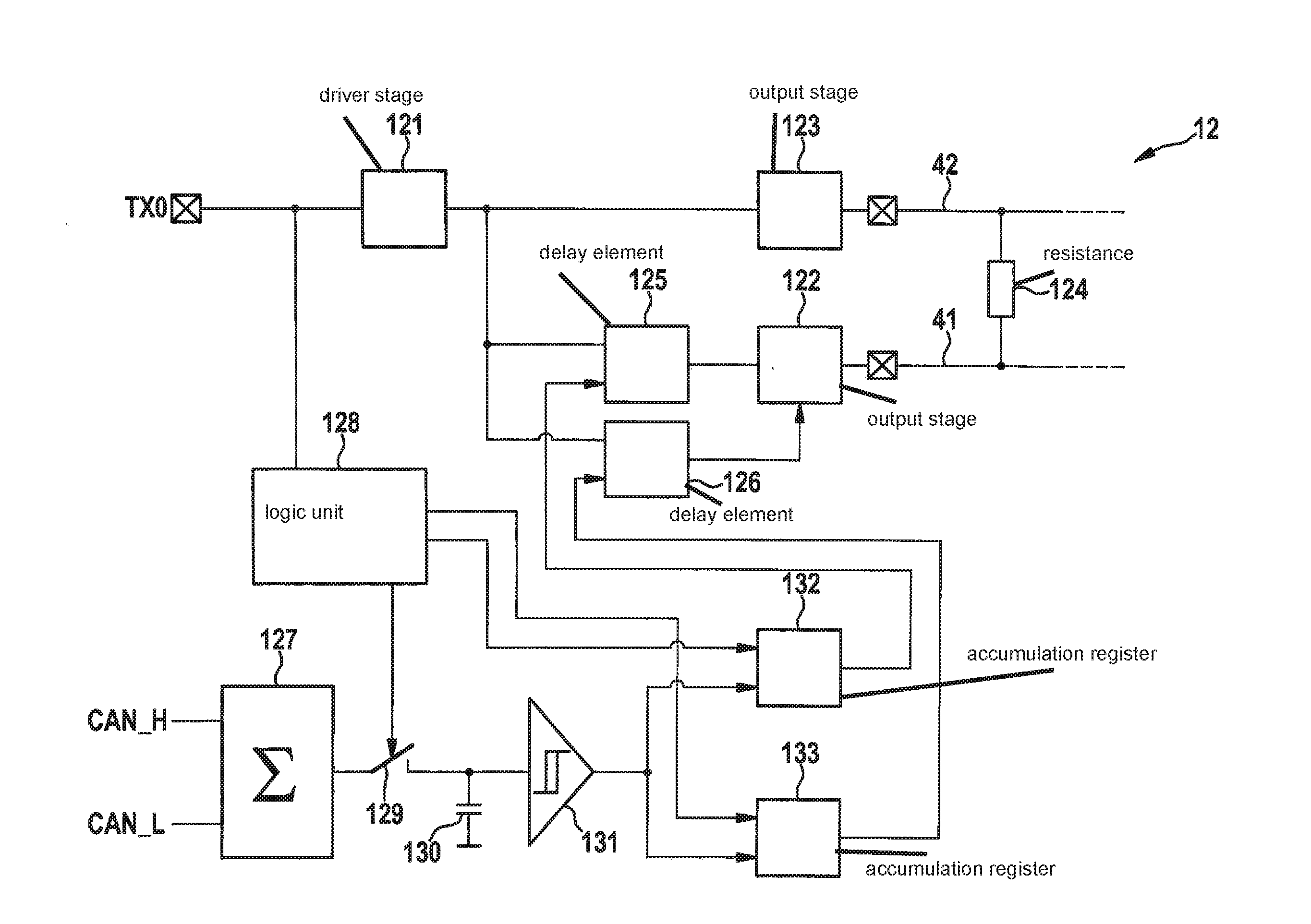
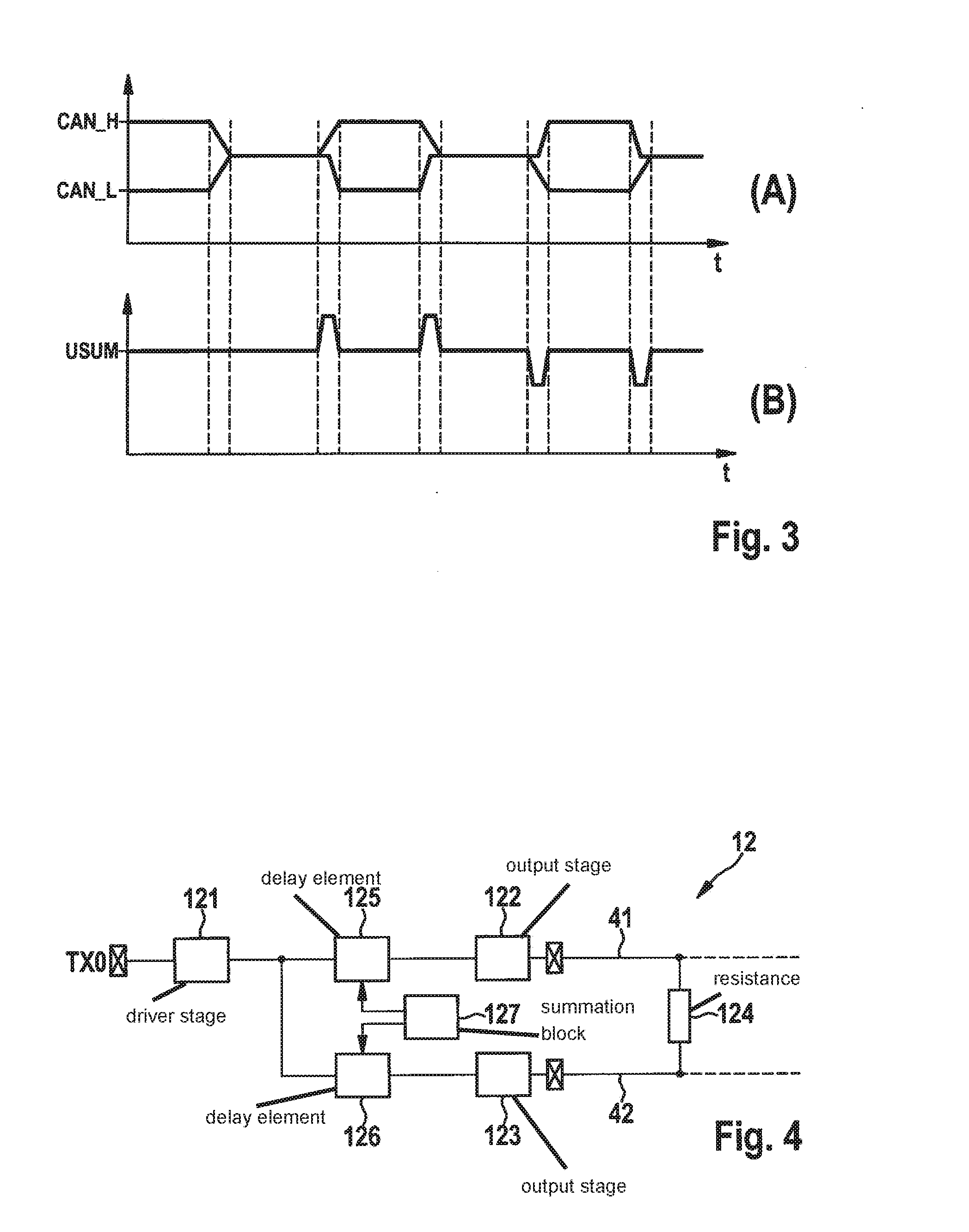
The present invention provides a subscriber station for a bus system and a method that can solve problems such as switching edge asymmetrization and interference peaks during a switching process. The subscriber station can match the delay times of different driver stages for CAN_H and CAN_L, even in long-term operation, to effectively compensate for interference peaks. It can also symmetrizate the signal switching edges to avoid current errors in different signal paths. The subscriber station includes a summation block, a capacitor, and an analog-digital converter to evaluate the sum voltage and count voltage peaks during the rising and falling signal edge. The method can evaluate the voltage peaks with regard to their amplitude level and temporal width, and use a first accumulation register and a second accumulation register to count voltage peaks in the sum voltage at the recessive-dominant transition and the dominant-recessive transition, respectively, to reduce delays in signal transmission.

Problems solved by technology

However, problems occur in the switching edges, because the driver stages for CAN_H and CAN_L have different delay times. These delays are a function of process conditions and of temperature, and are subject to aging.

Method used


Image

  • Subscriber station for a bus system and method for reducing line-conducted emissions in a bus system
  • Subscriber station for a bus system and method for reducing line-conducted emissions in a bus system
  • Subscriber station for a bus system and method for reducing line-conducted emissions in a bus system

Examples


Embodiment Construction

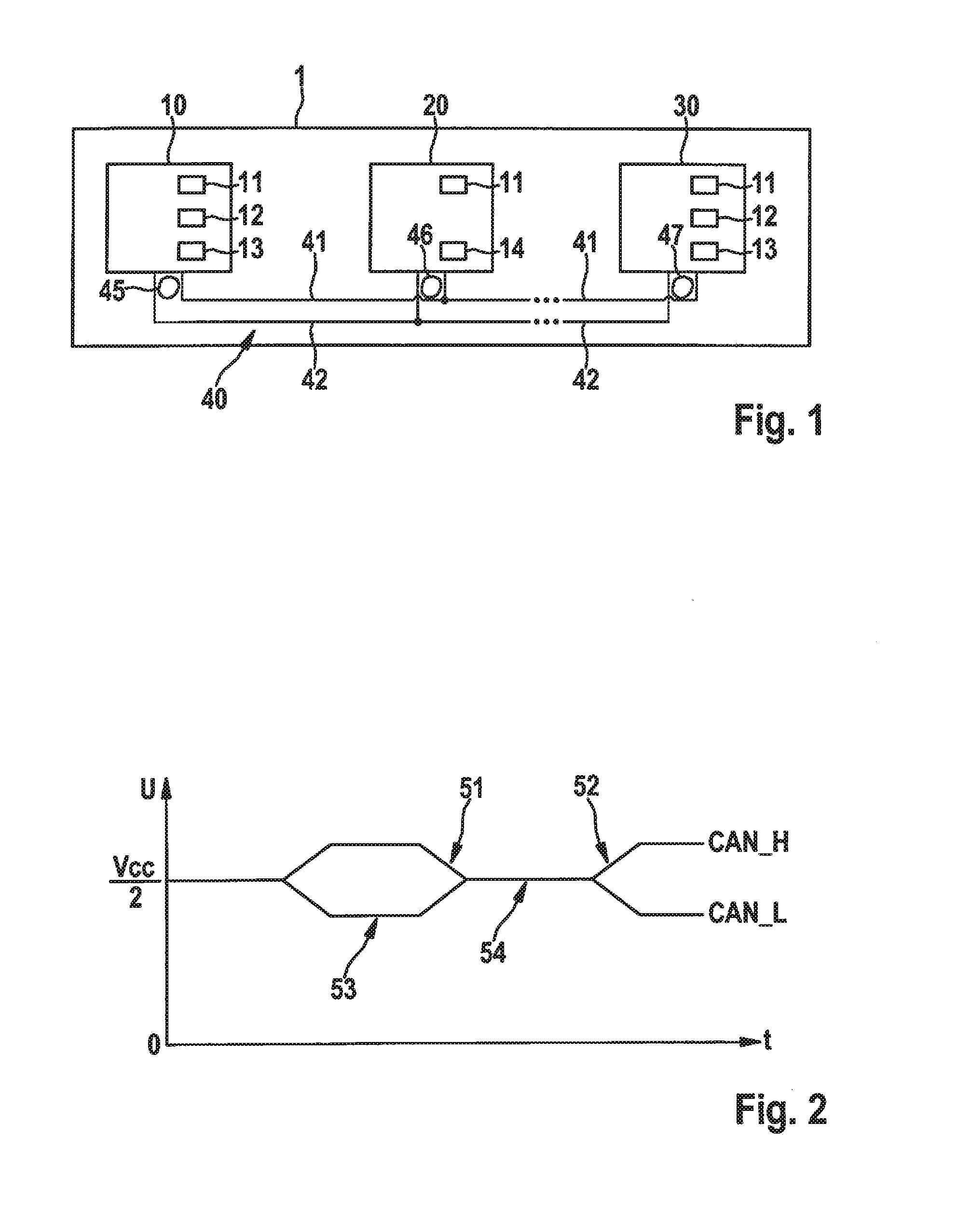
[0028]FIG. 1 shows a bus system 1 that can be for example a CAN bus system, a CAN-FD bus system, etc. Bus system 1 can be used in a vehicle, in particular a motor vehicle, an airplane, etc., or in a hospital, etc.

[0029]In FIG. 1, bus system 1 has a multiplicity of subscriber stations 10, 20, 30, each connected to a bus 40 with a first bus lead 41 and a second bus lead 42. Bus leads 41, 42 can also be named CAN_H and CAN_L, and are used to couple in the dominant level in the transmit state. Via bus 40, messages 45, 46, 47 can be transmitted in the form of signals between the individual subscriber stations 10, 20, 30. Subscriber stations 10, 20, 30 can for example be control devices or display devices of a motor vehicle.

[0030]As shown in FIG. 1, subscriber stations 10, 30 each have a communication control device 11, a transmit device 12, and a receive device 13. In contrast, subscriber station 20 has a communication control device 11 and a transceiver device 14. Transmit devices 12, r...


PUM


Abstract

A subscriber station for a bus system and a method for reducing line-conducted emissions in a bus system are provided. The subscriber station includes a first delay element for delaying a signal of a bus of the bus system and a second delay element for delaying a signal of a bus of the bus system, the delay time of the first and second delay element being capable of being digitally set as a function of the bus state or independently for rising and falling signal edges at the bus of the bus system in order to carry out a signal symmetrization during the rising and falling signal edge at the bus.

Description

FIELD[0001]The present invention relates to a subscriber station for a bus system and to a method for reducing line-conducted emissions in a bus system, in which a symmetrization is achieved of the switching edges that occur during a switching process of a bus signal.BACKGROUND INFORMATION[0002]The CAN bus is a differential bus system that places high demands on signal symmetrization. In this context, the better the signal symmetrization, the lower the radio-frequency interference radiation and the interference at a subscriber station, such as for example a car radio. The opposite-phase signals CAN_H and CAN_L must be controlled in such a way that their mean value deviates as little as possible from center voltage VCC5 / 2=2.5V.[0003]Currently, the signal symmetrization is achieved in that the resistances of the switches to ground GND and to the potential VCC5 are balanced in such a way that, in the dominant bus state, or dominant state of the bus, in which the difference voltage of t...

Claims


Application Information

Patent Timeline
Patent Type & Authority Applications(United States)
IPC IPC(8): G06F13/42G06F1/26
CPCG06F1/26G06F13/4291H04L25/0274H04L2012/40215H04L27/2614
Inventor WALKER, STEFFENPANNWITZ, AXELHEHEMANN, INGO
Owner ROBERT BOSCH GMBH
Learn More