Eureka AIR delivers breakthrough ideas for toughest innovation challenges, trusted by R&D personnel around the world.

Microwave drying method of honeycomb formed body

a technology of microwave drying and honeycomb, which is applied in the field of microwave drying method of honeycomb formed body, can solve the problems of overheating of the center part of the honeycomb formed body, and deformation of cells at the center part of such a honeycomb formed body, etc., to achieve suppressed cell deformation at the center part of the formed body, the effect of deformation

Active Publication Date: 2016-10-06
NGK INSULATORS LTD
View PDF2 Cites 3 Cited by
  • Summary
  • Abstract
  • Description
  • Claims
  • Application Information

AI Technical Summary

Benefits of technology

The present invention provides a microwave drying method for honeycomb formed bodies that prevents deformation of cells at the center part of the body due to pressure caused by delayed drying. The method aims to improve the penetration of microwaves into the center part of the body by using lower frequency microwaves or placing a microwave reflector to reduce temperature gradients inside the formed body. The technical effect of this invention is to prevent defects in the shape of the honeycomb formed body during the drying process.

Problems solved by technology

Since the strength of the honeycomb formed body having a thinner partition wall deteriorates, cells at the center part of such a honeycomb formed body tend to be deformed due to the pressure.
Such deformation of the cells at the center part of the honeycomb formed body is transmitted to the end-face part of the honeycomb formed body along the cell direction, which greatly degrades the mechanical strength of the honeycomb structure.
Meanwhile, when a conventional honeycomb formed body containing more water is dried at 915 MHz, microwaves penetrate into the center part of the honeycomb formed body excessively, so that a phenomenon is found that the center part of the honeycomb formed body is overheated.
In this case, however, since microwaves are incident only from the vertical direction of the honeycomb formed body, deformation of cells will occur inside of the honeycomb formed body similarly to the related art of the present application described later, and so such a technique cannot be applied.

Method used


Image

  • Microwave drying method of honeycomb formed body
  • Microwave drying method of honeycomb formed body
  • Microwave drying method of honeycomb formed body

Examples


examples

[0051](1) Honeycomb Formed Body

[0052]For Examples 1 to 4 and Comparative Examples 1 to 5, the honeycomb formed bodies were used, including the cordierite component formed under the same condition. Since the details of the forming step to form such honeycomb formed bodies are well known, their detailed descriptions are omitted. The honeycomb formed bodies of Examples 1 to 3 and Comparative Examples 1, 3 and 4 had a honeycomb diameter of 385 mm, and the honeycomb formed bodies of Example 4 and Comparative Examples 2 and 5 had a honeycomb diameter of 320 mm. They had a honeycomb length of 330 mm. The ratio of water content (water-containing ratio) included in the honeycomb formed body with reference to the weight of the honeycomb formed body before drying was 24%. Note here that these dimensions were values before drying.

[0053](2) Microwave Drying Conditions

[0054]The honeycomb formed bodies formed by the above (1) according to Examples 1 to 4 and Comparative Examples 1 to 5 were introd...


PUM

PropertyMeasurementUnit
frequencyaaaaaaaaaa
temperatureaaaaaaaaaa
lengthaaaaaaaaaa

Abstract

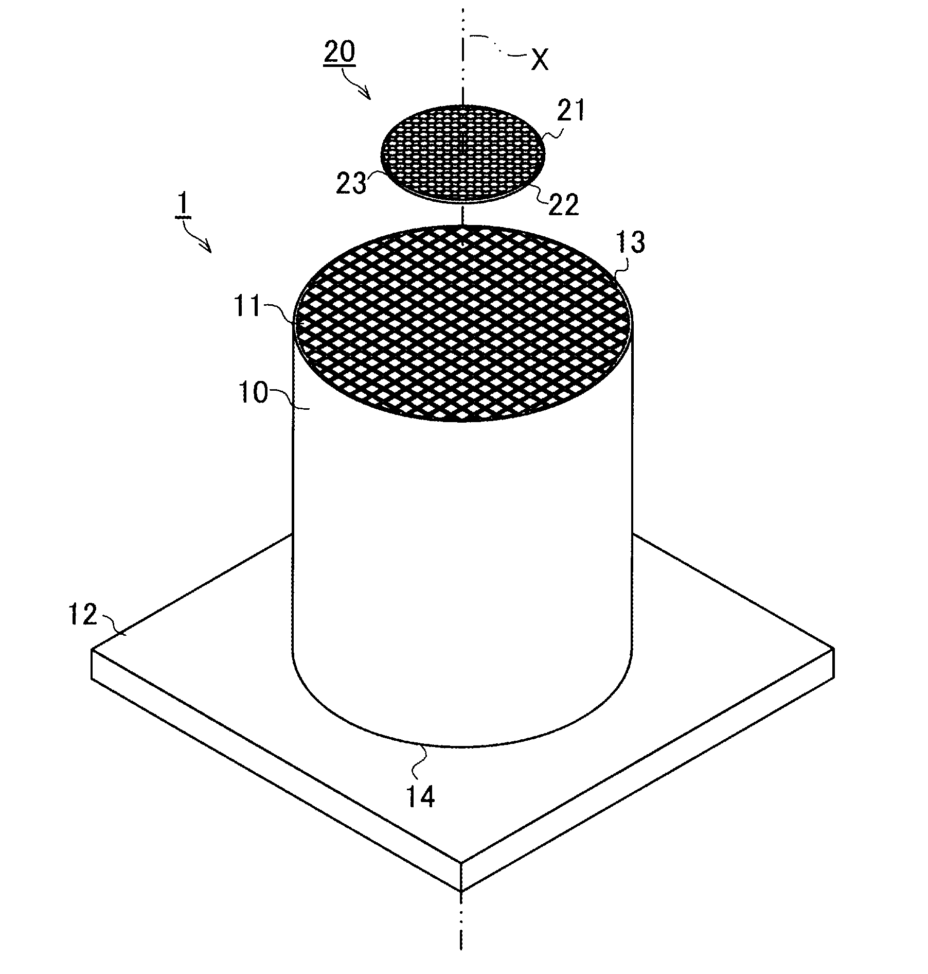
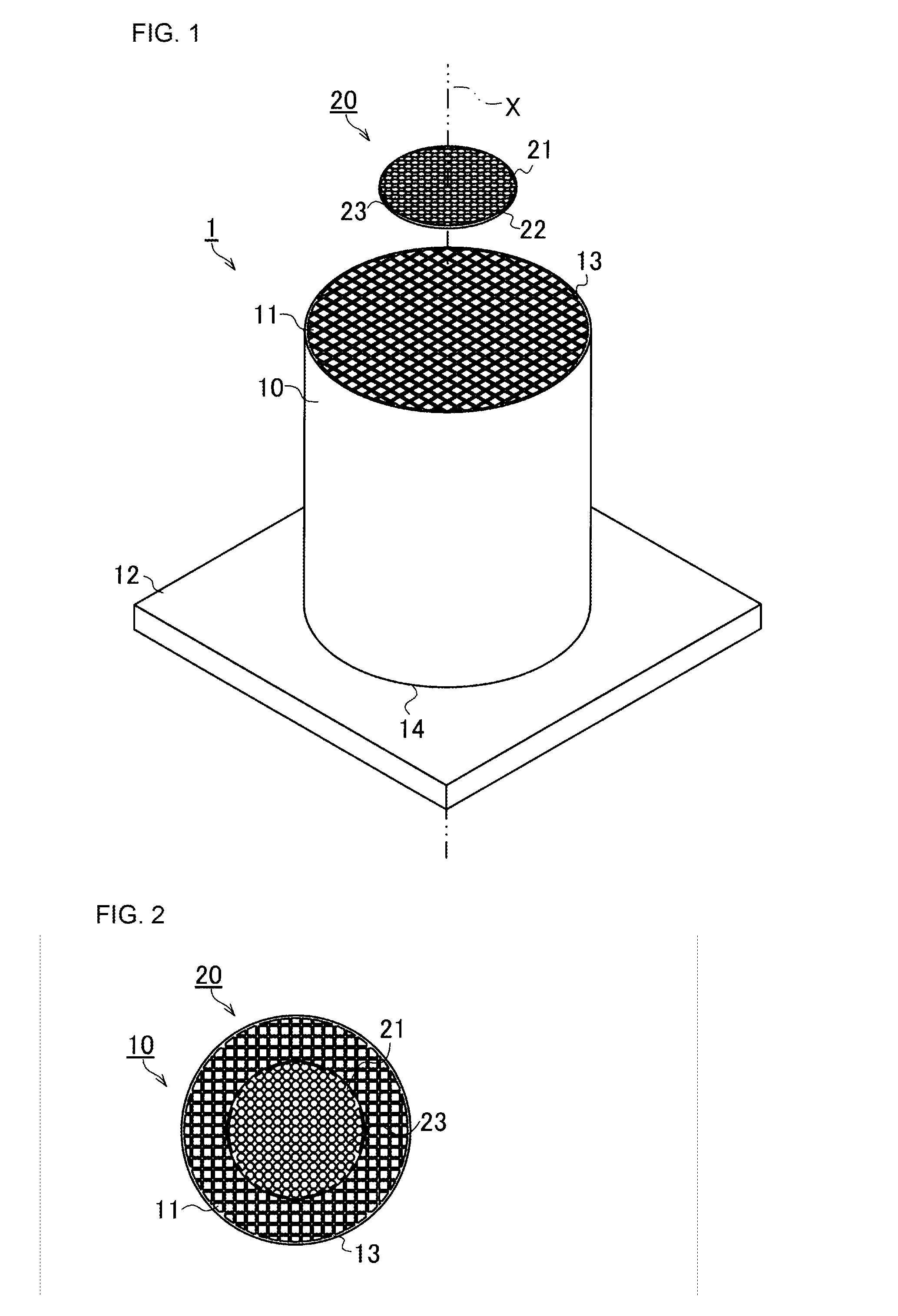
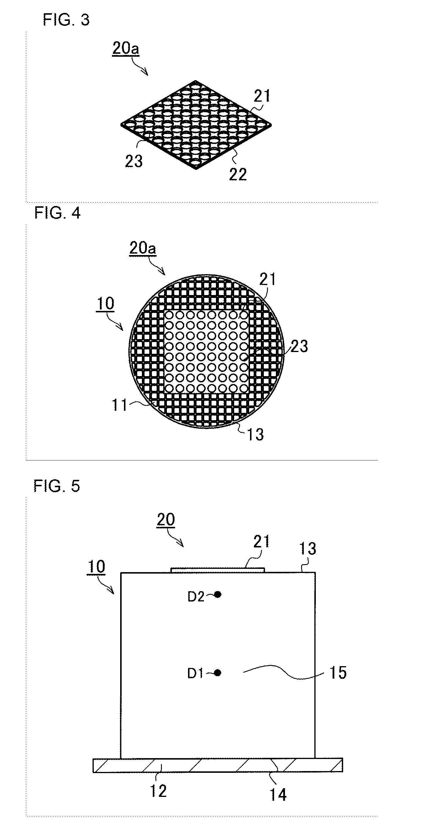
A microwave drying method of a honeycomb formed body includes: an introduction step of disposing the honeycomb formed body while keeping an axis direction of cells of the honeycomb formed body vertically and introducing the honeycomb formed body into a drying furnace capable of irradiating with microwaves; a reflector placing step of placing a microwave reflector above the honeycomb formed body, the microwave reflector including a reflecting face having a coverage factor to an area of an end face of the honeycomb formed body that is 15% to 30%; and a microwave drying step of irradiating the honeycomb formed body with the microwaves of 915 MHz in frequency from above to dry the honeycomb formed body.

Description

[0001]The present application is an application based on JP 2015-071545 filed on Mar. 31, 2015 with the Japan Patent Office, the entire contents of which are incorporated herein by reference.BACKGROUND OF THE INVENTION[0002]1. Field of the Invention[0003]The present invention relates to a microwave drying method of a honeycomb formed body. More specifically, the present invention relates to a microwave drying method of a honeycomb formed body to dry a honeycomb formed body by means of microwaves.[0004]2. Description of the Related Art[0005]Conventionally, honeycomb structures made of ceramic have been used for a wide range of purposes, including a catalyst carrier to purify exhaust gas from automobiles, a filter to remove diesel particulates, and a heat storage member for combustion devices, for example. Such a honeycomb structure made of ceramic (hereinafter simply called a “honeycomb structure”) is manufactured by cutting a honeycomb formed body, which is prepared by extruding a f...

Claims


Application Information

Patent Timeline
Patent Type & Authority Applications(United States)
IPC IPC(8): B28B11/24F26B3/347
CPCB28B11/241F26B2210/02F26B3/347F26B23/04B28B11/243H05B6/80H05B2206/046
Inventor ASAKURA, NORIHIROOKUMURA, KENSUKEHAYASHI, SEIICHIRO
Owner NGK INSULATORS LTD
Why Eureka
Eureka Blog
Learn More