
Method and device for operating beam mode in wireless communication system

a wireless communication system and beam mode technology, applied in wireless communication, baseband system details, electromagnetic repeaters, etc., can solve the problem of nearly unavailability of channel status, and achieve the effect of reducing uplink overhead, effective operation of beam mode in wireless communication system, and reducing calculation complexity of terminals

Active Publication Date: 2016-10-06
SAMSUNG ELECTRONICS CO LTD
View PDF10 Cites 29 Cited by
  • Summary
  • Abstract
  • Description
  • Claims
  • Application Information

AI Technical Summary

Benefits of technology

The present invention provides a method for efficiently operating a beam mode in a wireless communication system. This method reduces uplink overhead, simplifies the calculations of terminals, and reduces power consumption. Additionally, it improves the flexibility of selecting a transmission beam ID of a base station.

Problems solved by technology

However, since the super high frequency region has a great path loss, it is required to improve a beamforming gain by using a plurality of antennas at a terminal and a base station.
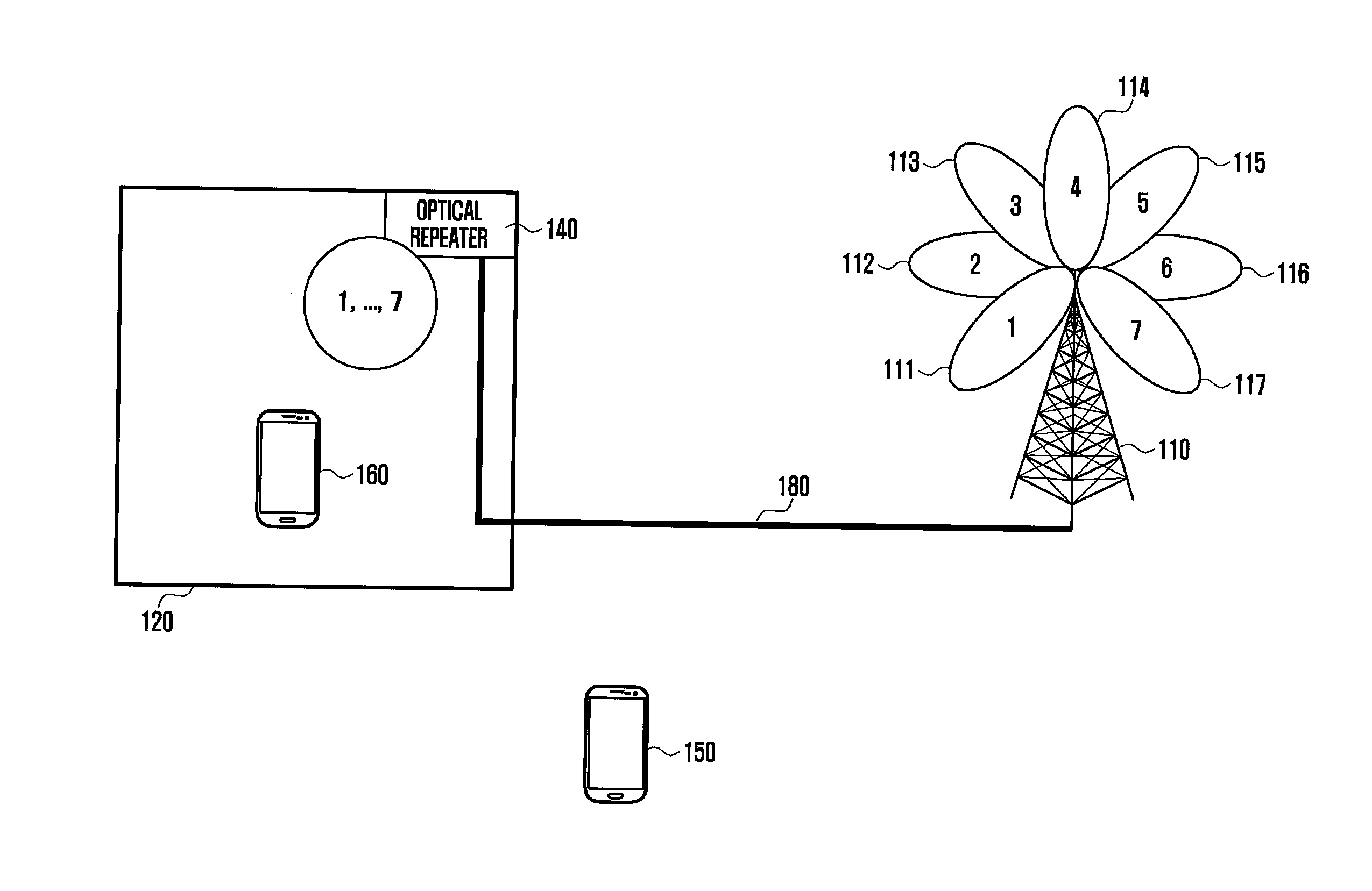
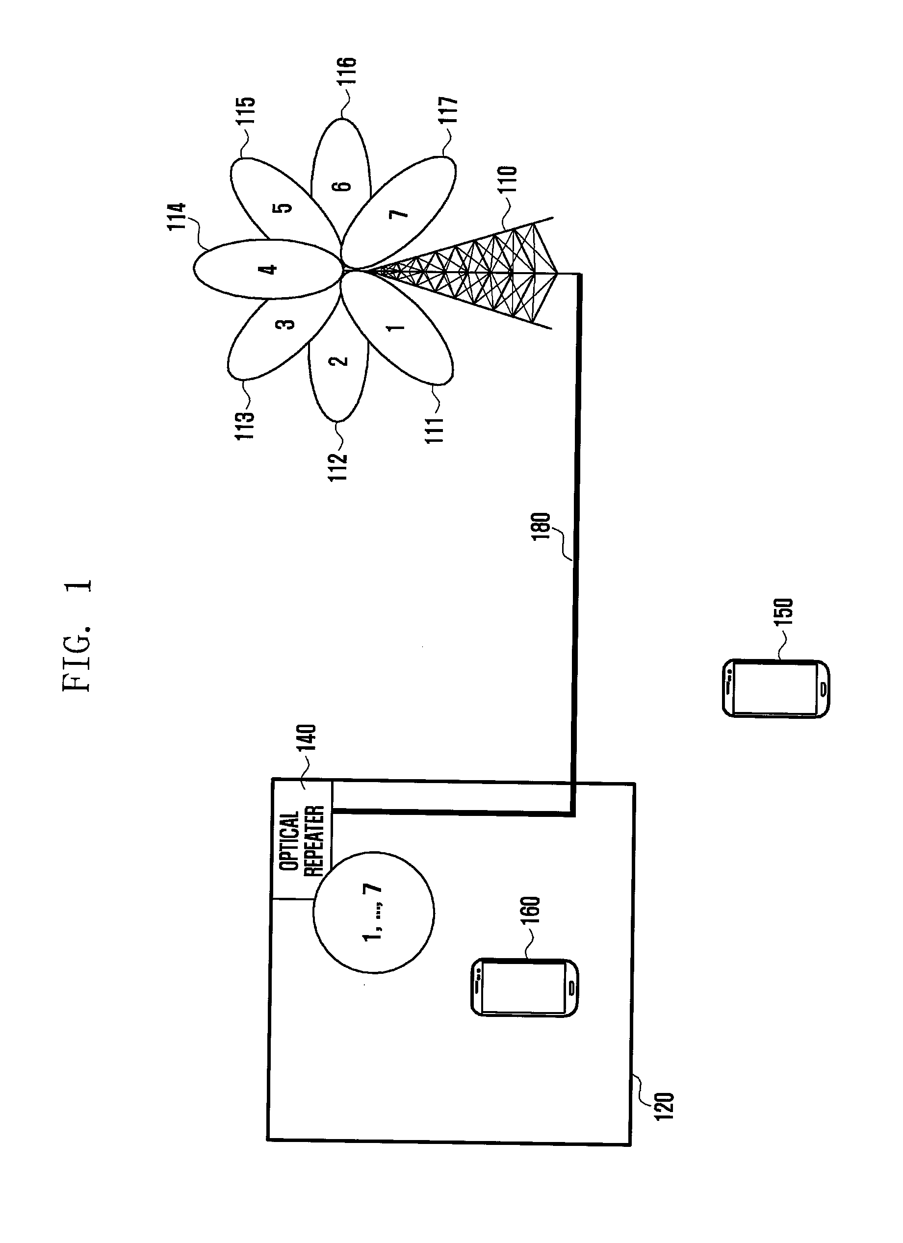
Namely, the channel status is nearly unvaried in case of all beams operated by the base station.

Method used


Image

  • Method and device for operating beam mode in wireless communication system
  • Method and device for operating beam mode in wireless communication system
  • Method and device for operating beam mode in wireless communication system

Examples


Embodiment Construction

[0021]Hereinafter, embodiments of the present invention will be described with reference to the accompanying drawings. In this disclosure, well known functions or structures may not be described or illustrated in detail to avoid obscuring the subject matter of the present invention. Additionally, the terms used herein are defined in view of functions in this invention and may be varied according to user or operator's intention or custom. Therefore, such a definition should be made on the basis of the contents of this disclosure.

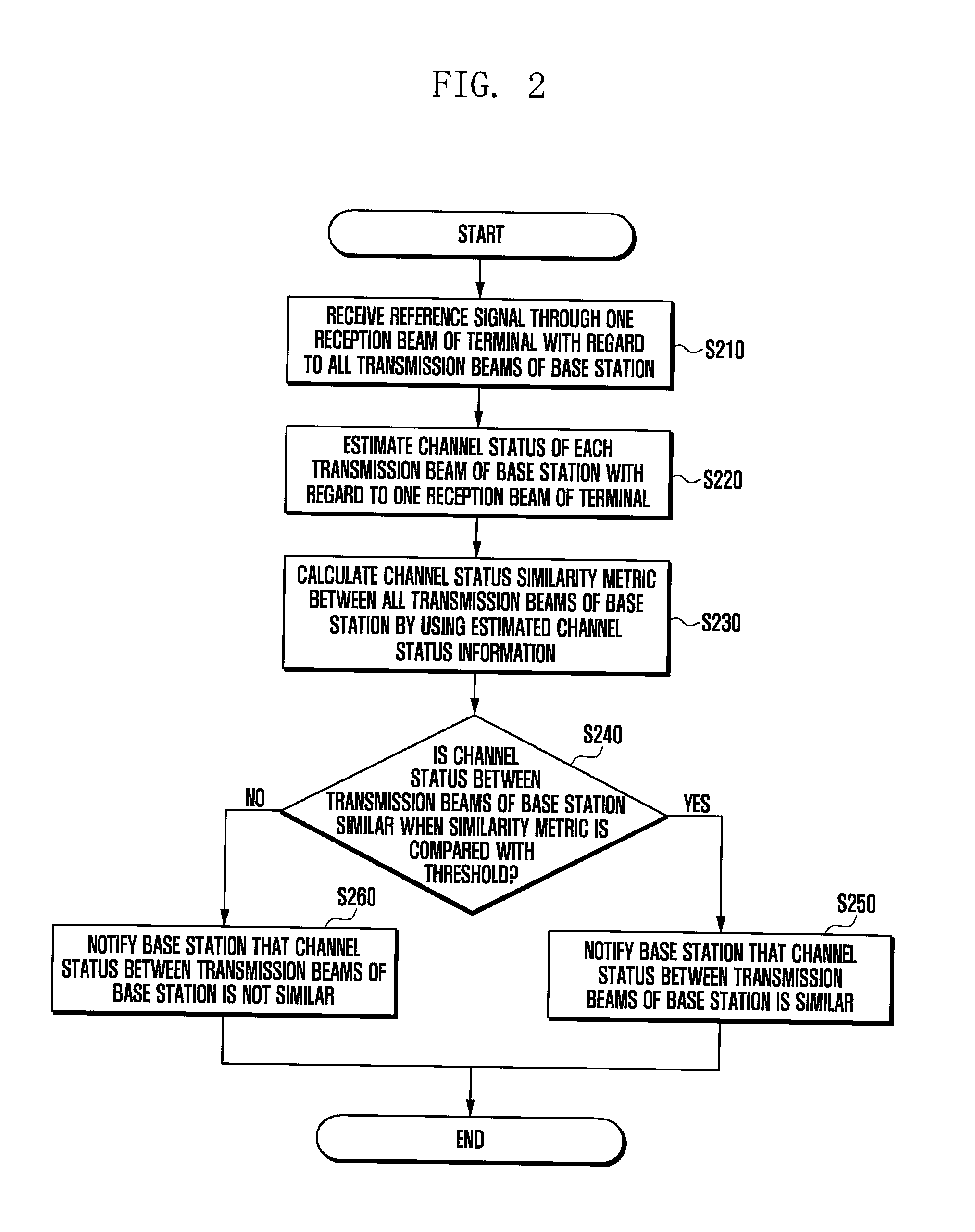
[0022]Hereinafter, embodiments of the present invention will be described with regard to a method, together with a related procedure, in which a base station allocates a specific transmission or reception beam thereof to a terminal depending on a channel status when the base station and the terminal perform communication by using several beams in a wireless communication system.

[0023]Hereinafter, this invention will be described using, as an example, a wirele...


PUM


Abstract

According to one embodiment of the present invention, provided is a method for setting a beam mode of a base station in a wireless communication system, comprising the steps of: selecting the beam mode for at least one terminal, which is serviced by the base station, on the basis of a channel state of a transmission beam or a reception beam of the base station; transmitting, to the terminal, a control message including selected beam mode information; and performing data communication with the terminal by using the transmission beam and the reception beam corresponding to the selected mode. In addition, according to one embodiment of the present invention, provided is a communication method of the terminal in the wireless communication system, comprising the steps of: receiving a beam mode setting message from the base station; setting either a beam fixation mode or a beam sweeping mode on the basis of the received beam mode setting message; and performing data communication with the base station on the basis of the set mode.

Description

TECHNICAL FIELD[0001]The present invention relates to a method and device for operating a beam mode in a wireless communication system.BACKGROUND ART[0002]As one of techniques to increase communication capacity in the next-generation communication, a broadband in a super high frequency region may be used for data transmission and reception. However, since the super high frequency region has a great path loss, it is required to improve a beamforming gain by using a plurality of antennas at a terminal and a base station. In this case, since a beam has directivity, the base station and the terminal adjust a beam in a specific direction for communication.[0003]Currently in the cellular network using a frequency region of 5 GHz or less, there is a radio shadow area where a signal of the base station fails to arrive. In order to solve this, a repeater is installed in the radio shadow area. Such a repeater amplifies the signal received from the base station and retransmits it to the termin...

Claims


Application Information

Patent Timeline
IPC IPC(8): H04B7/06H04L25/02H04B10/29H04W88/08H04W72/04
CPCH04B7/0695H04W88/08H04B7/063H04B10/29H04L25/0202H04W72/046H04B10/25752H04W72/542H04B7/02
Inventor JEONG, CHEOLYU, HYUNKYUPARK, JEONGHOKIM, JAEWON
Owner SAMSUNG ELECTRONICS CO LTD
Learn More