
Light source unit for endoscope and endoscopy system

a technology of endoscope and light source unit, which is applied in the field of endoscope and endoscope system light source unit, which can solve the problems of difficult discrimination therebetween and difficult to discriminate therebetween

Active Publication Date: 2016-10-13
FUJIFILM CORP
View PDF6 Cites 6 Cited by
  • Summary
  • Abstract
  • Description
  • Claims
  • Application Information

AI Technical Summary

Benefits of technology

The present invention provides a light source and an endoscopy system that can identify different colored dyes in an endoscopy image. This is accomplished by using a semiconductor illuminant and a band limiting section that reduces the light intensity in a specific wavelength range where the first dye has a high reflectance and the second dye has low reflectance. This allows for the clarification of color differences between the two dyes. The band limiting section is triggered by a threshold value that is determined based on the optical reflectance of the first dye. The invention improves the quality of endoscopy images and enhances the ability of medical professionals to diagnose and treat patient illnesses.

Problems solved by technology

For example, when the illumination light contains less red band wavelength components, both pyoktanin and indigocarmine will be observed in blue, making it difficult to discriminate therebetween.
On the contrary, when the wavelength components of the illumination light range from the red band to the infrared region, both pyoktanin and indigocarmine will be observed in violet, making it difficult to discriminate therebetween.

Method used


Image

  • Light source unit for endoscope and endoscopy system
  • Light source unit for endoscope and endoscopy system
  • Light source unit for endoscope and endoscopy system

Examples


Embodiment Construction

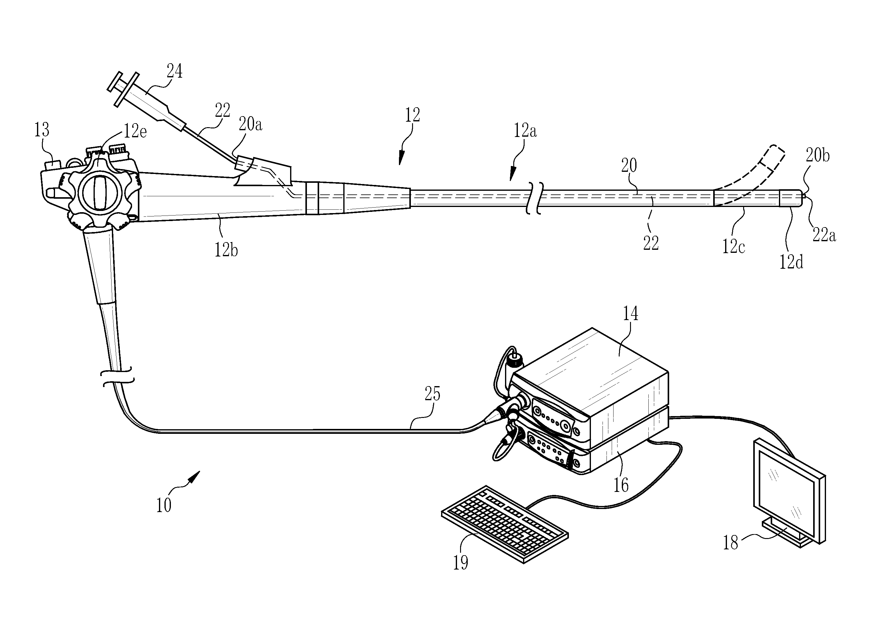
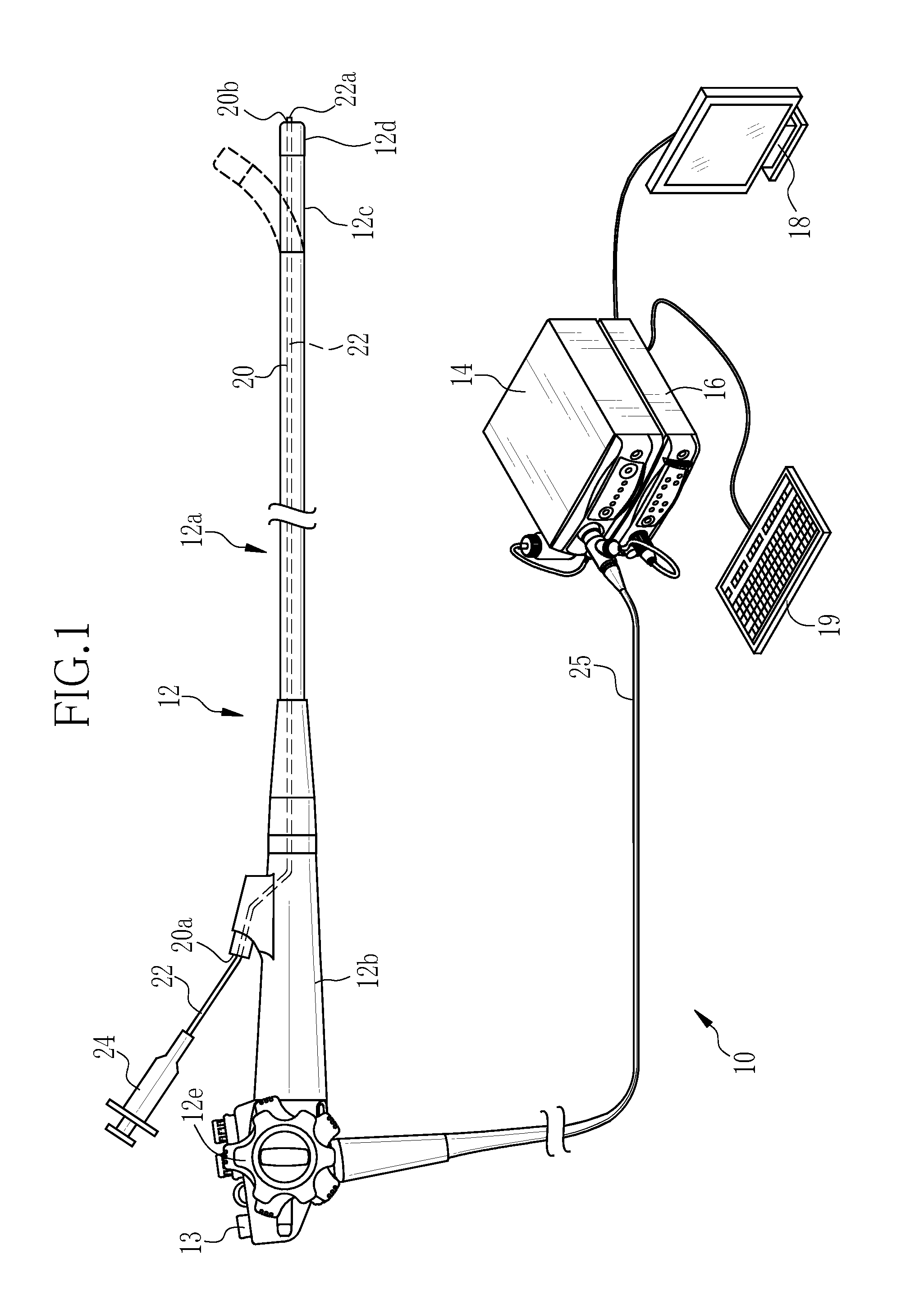
[0033]In FIG. 1, an endoscopy system 10 has an endoscope 12, a light source unit for the endoscope 14, a processor unit 16, a monitor 18 and a console 19. A universal cord 25 connects the endoscope 12 optically to the light source unit 14 and electrically to the processor unit 16.

[0034]The endoscope 12 has an insertion section 12a is to be inserted in a test body, a control section 12b provided on a proximal end of the insertion section 12a, a bending section 12c provided on a distal end of the insertion section 12a, and a tip portion 12d provided at a distal end of the bending section 12c. Operating an angle-adjusting knob 12e of the control section 12b bends the bending section 12c, thereby directing the tip portion 12d to a desired orientation. The control section 12b is further provided with other members than the angle-adjusting knob 12e, such as a zooming section 13.

[0035]The processor unit 16 is electrically connected to the monitor 18 and the console 19. The monitor 18 is a ...


PUM


Abstract

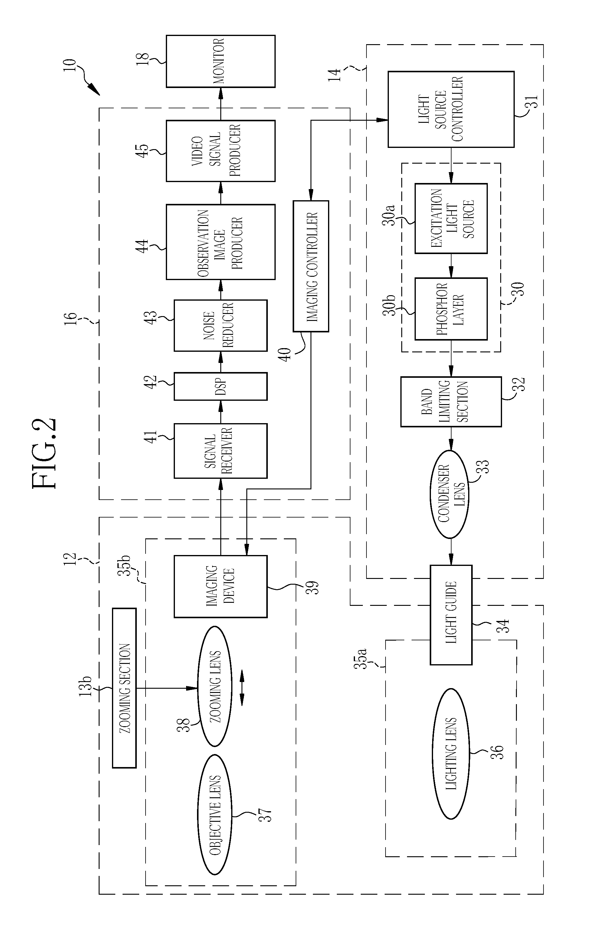
Provided are a light source unit for an endoscope and an endoscopy system, which clarify the color difference between a first dye and a second dye in an observation image. The light source unit has a white LED light source and a band limiting section. The white LED light source has an excitation light source that emits blue excitation light and a phosphor layer that emits yellow fluorescence upon receipt of the excitation light. As a mixture of the fluorescence and part of the excitation light, the white LED light source outputs light having an intensity spectrum continuous across blue, green and red regions. The band limiting section reduces part of the output light in a wavelength band of not lower than a threshold. The threshold is not less than 650 nm. At the threshold, the first dye (pyoktanin) has an optical reflectance of not less than a constant value, whereas the second dye (indigocarmine) has an optical reflectance of substantially zero.

Description

CROSS-REFERENCE TO RELATED APPLICATIONS[0001]This application claims priority under 35 U.S.C §119(a) to Japanese Patent Application No. 2015-081718 filed on Apr. 13, 2015. The above application is hereby expressly incorporated by reference, in its entirety, into the present application.BACKGROUND OF THE INVENTION[0002]1. Field of the Invention[0003]The present invention relates to a light source unit for endoscopes and an endoscopy system.[0004]2. Description Related to the Prior Art[0005]In the medical field, endoscopy systems, which are each equipped with an endoscope, a light source unit for the endoscope and a processor unit, are widely used for diagnoses. The light source unit emits illumination light, which travels through a light guide inside the endoscope and is projected from a tip portion of the endoscope toward an observation object. The tip portion of the endoscope has an imaging device integrated therein so that light returned from the observation object is received on ...

Claims


Application Information

Patent Timeline
IPC IPC(8): A61B1/06F21V9/08A61K49/00A61B1/04A61B1/00A61M31/00F21V9/16H04N5/225
CPCA61B1/0653F21V9/16F21V9/08H04N5/2256A61B1/0684A61B1/043A61B2090/309A61M31/005A61K49/006A61K49/0023A61K49/0021F21Y2101/02H04N2005/2255A61B1/00009A61B1/00163A61B1/05A61B1/0661A61B1/31A61B1/0646F21Y2101/00H04N23/56H04N23/555
Inventor KUBO, MASAHIRO
Owner FUJIFILM CORP
Learn More