Fuel supply device and fuel supply method for internal combustion engine

a fuel supply device and internal combustion engine technology, applied in the direction of fuel injection apparatus, charge feed system, electric control, etc., can solve the problems of increasing the variation of the quantity of partial lift injection, deteriorating combustion of the internal combustion engine, etc., and achieves the effect of increasing the variation of the quantity of fuel injection and high level of accuracy

Active Publication Date: 2016-10-13
TOYOTA JIDOSHA KK
View PDF5 Cites 5 Cited by
  • Summary
  • Abstract
  • Description
  • Claims
  • Application Information

AI Technical Summary

Benefits of technology

[0007]A partial lift injection is known as a technique for realizing high-accuracy micro injection. During the partial lift injection, the fuel injection is performed such that the injection is terminated before a valve body of the fuel injection valve reaches full opening. The valve body of the fuel injection valve performs a bounce motion because of a c

Problems solved by technology

Accordingly, when the operation sound suppression control is carried out while the partial lift injection is in progress, the injec

Method used


Image

  • Fuel supply device and fuel supply method for internal combustion engine
  • Fuel supply device and fuel supply method for internal combustion engine
  • Fuel supply device and fuel supply method for internal combustion engine

Examples


first embodiment

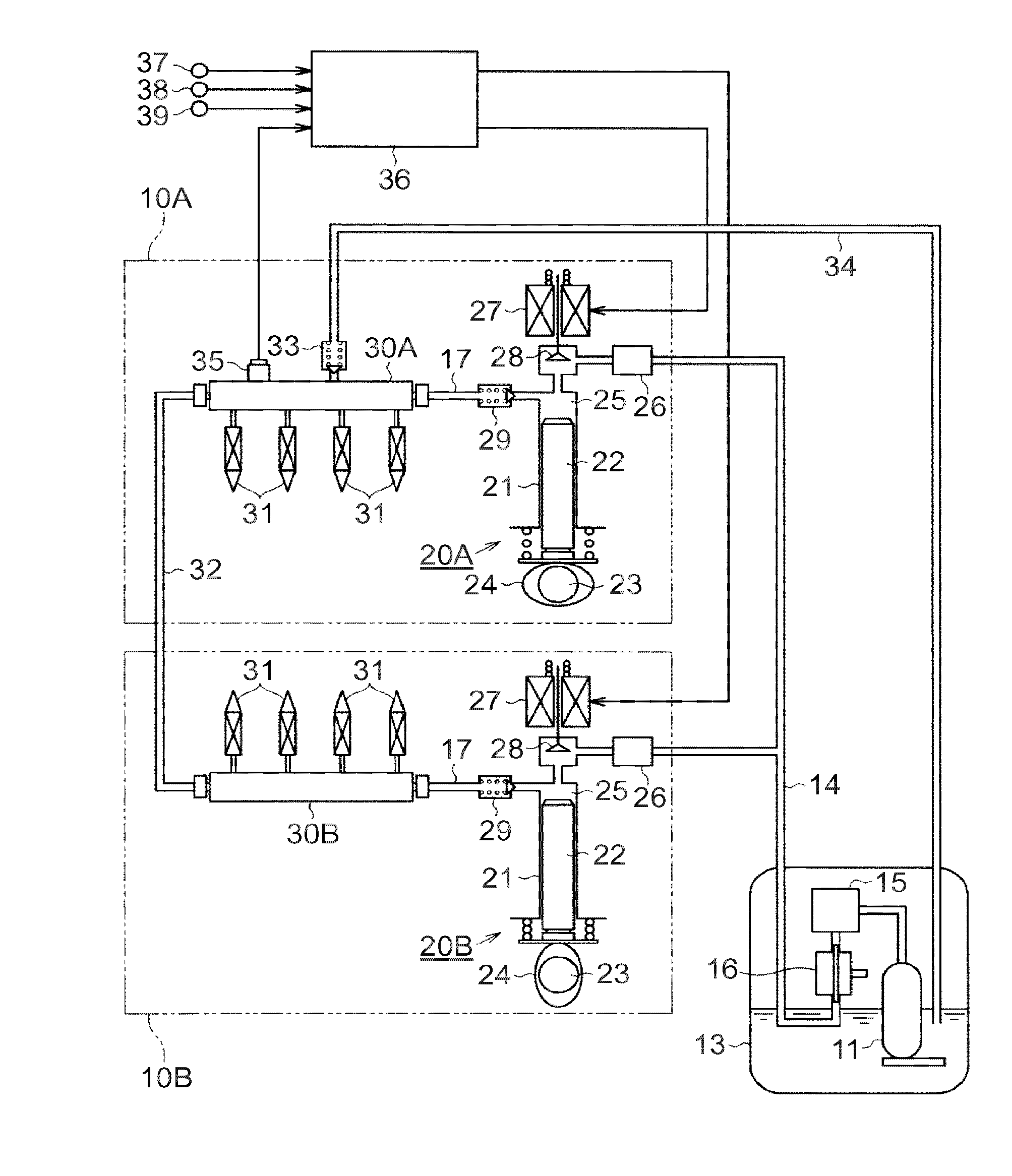
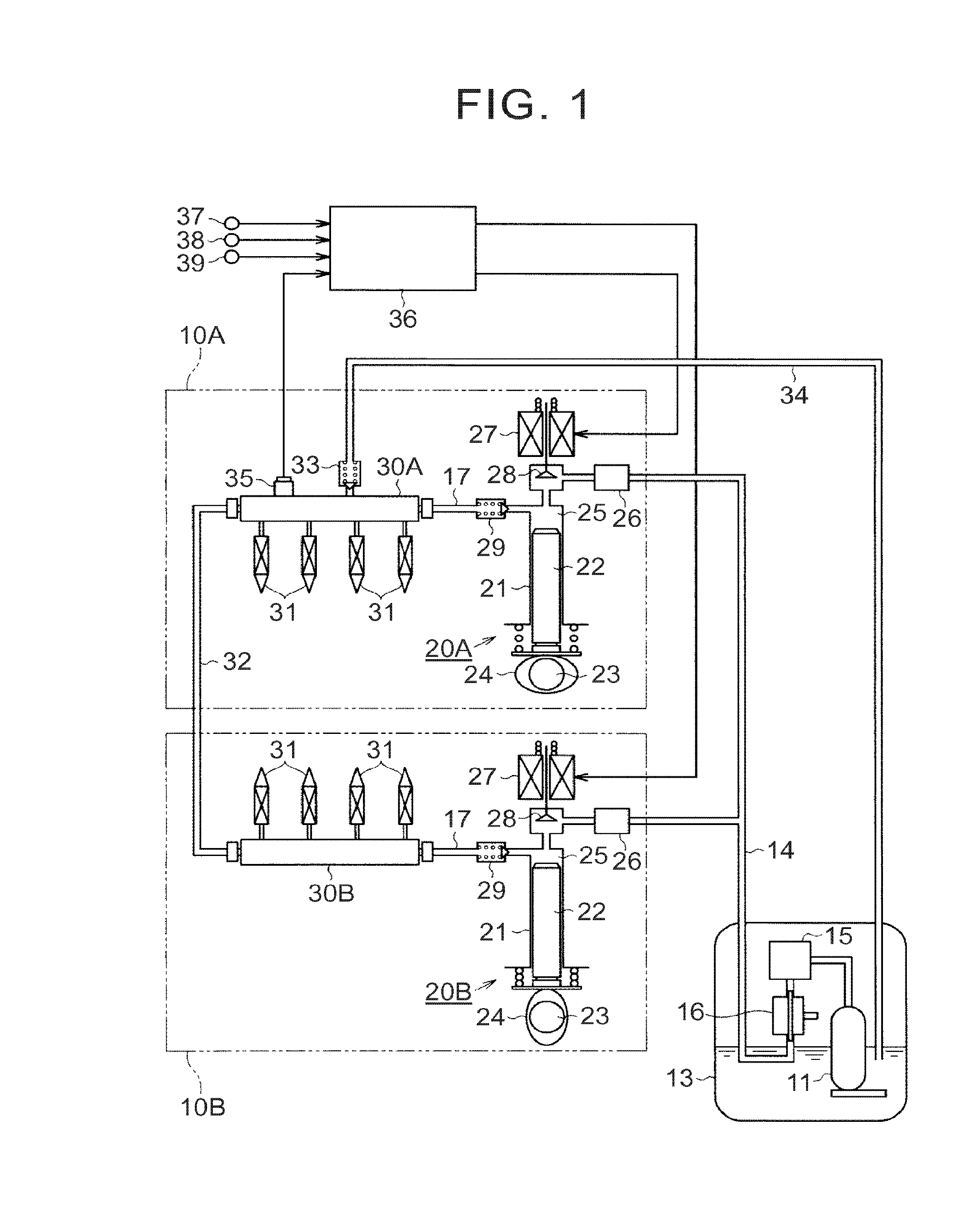
[0024]Hereinafter, a fuel supply device for an internal combustion engine will be described in detail with reference to FIGS. 1 to 7.

[0025]As illustrated in FIG. 1, the internal combustion engine to which the fuel supply device according to this embodiment is applied is a V-type eight-cylinder internal combustion engine that has two banks, one being a first bank 10A and the other being a second bank 10B, and is provided with four cylinders in each of the banks.

[0026]The fuel supply device according to this embodiment is provided with a feed pump 11 and two high-pressure fuel pumps 20A, 20B that are disposed in the first bank 10A and the second bank 10B, respectively. The feed pump 11 pumps a fuel in a fuel tank 13 and sends the fuel to both the high-pressure fuel pumps 20A, 20B through a low-pressure fuel passage 14. A filter 15 and a pressure regulator 16 are disposed on the low-pressure fuel passage 14. The filter 15 filters impurities in the fuel. The pressure regulator 16 return...

second embodiment

[0061]A second embodiment will be described below. As illustrated in FIG. 8, in this embodiment, the operation sound suppression control is carried out by the opening and closing control for each of the electromagnetic valves 28 being performed such that each of the two high-pressure fuel pumps 20A, 20B intermittently performs the pressurizing operation. In the case of FIG. 8, the closing of the electromagnetic valve 28 for the fuel discharge is performed during only one of two pressurization strokes in each of the high-pressure fuel pumps 20A, 20B. In other words, during the operation sound suppression control, both the high-pressure fuel pumps 20A, 20B alternately perform the pressurizing operation and the pause of the pressurizing operation for every other operation cycle. Even in this case, the opening and closing frequency of the electromagnetic valves 28 of the entire fuel pressurization device is reduced and the operation sound thereof decreases. Even in this case, the fuel d...

third embodiment

[0062]A third embodiment will be described below. As illustrated in FIG. 9, the operation sound suppression control can be performed even in a fuel supply device for an internal combustion engine in which the fuel pressurization device is provided with only one high-pressure fuel pump. In the example of FIG. 9, the pressurizing operation is performed for each operation cycle during the normal control whereas, during the operation sound suppression control, the opening and closing control for the electromagnetic valve 28 is performed such that the pressurizing operation and the pause of the pressurizing operation are alternately performed for every other operation cycle. Even in this case, the opening and closing frequency of the electromagnetic valves 28 is reduced and the operation sound thereof decreases, but the fuel discharge amount per pressurizing operation increases and the fuel pressure pulsation increases. Accordingly, the combustion deterioration can be suppressed and the ...


PUM


Abstract

A fuel supply device includes an injector, a fuel pressurization device and an ECU. The fuel pressurization device includes an electromagnetic valve. The fuel pressurization device is configured to pressurize a fuel in accordance with opening/closing of the electromagnetic valve and discharge the fuel toward the injector. The ECU is configured: to control the opening/closing of the electromagnetic valve to adjust the fuel amount discharged toward the injector; to execute an operation sound suppression control during a low-load operation of an engine by reducing an opening/closing frequency of the electromagnetic valve and increasing the fuel amount discharged for each opening/closing of the electromagnetic valve; not to execute the operation sound suppression control when a partial lift injection is in progress; and to execute the operation sound suppression control when the partial lift injection is not in progress.

Description

INCORPORATION BY REFERENCE[0001]The disclosure of Japanese Patent Application No. 2015-082014 filed on Apr. 13, 2015 including the specification, drawings and abstract is incorporated herein by reference in its entirety.BACKGROUND OF THE INVENTION[0002]1. Field of the Invention[0003]This disclosure relates to a fuel supply device and a fuel supply method for an internal combustion engine that is provided with a high-pressure fuel pump which pressurizes a fuel pumped from a fuel tank and supplies the fuel to a fuel injection valve.[0004]2. Description of Related Art[0005]A high-pressure fuel pump is disposed in an internal combustion engine such as an in-cylinder injection-type internal combustion engine. The high-pressure fuel pump pressurizes a fuel pumped from a fuel tank and supplies the fuel to a fuel injection valve. An electromagnetic valve is disposed in the high-pressure fuel pump. The amount of the fuel that is discharged from the high-pressure fuel pump is adjusted by open...

Claims


Application Information

Patent Timeline
IPC IPC(8): F02M59/36F02M59/02F02M61/08F02M51/04
CPCF02M59/366F02M61/08F02M59/027F02M51/04F02D41/08F02D41/3845F02D2041/3881F02M59/466F02M63/029F02M2200/09
Inventor NAKANO, TOMOHIRO
Owner TOYOTA JIDOSHA KK
Why Eureka
Try Eureka