
Method and system for characterizing the agglomeration or speed of particles contained in a liquid, such as blood particles

a technology of particle agglomeration and liquid, which is applied in the field of method and system for characterizing the agglomeration or speed of particles contained in liquid, and can solve the problem of relatively bulky system

Active Publication Date: 2016-10-13
COMMISSARIAT A LENERGIE ATOMIQUE ET AUX ENERGIES ALTERNATIVES
View PDF4 Cites 3 Cited by
  • Summary
  • Abstract
  • Description
  • Claims
  • Application Information

AI Technical Summary

Benefits of technology

The invention is about a way to characterize liquids while keeping the system that is used to characterize them small. This makes it easier to observe the liquid without carrying around a big system.

Problems solved by technology

However, such a system is relatively bulky.

Method used


Image

  • Method and system for characterizing the agglomeration or speed of particles contained in a liquid, such as blood particles
  • Method and system for characterizing the agglomeration or speed of particles contained in a liquid, such as blood particles
  • Method and system for characterizing the agglomeration or speed of particles contained in a liquid, such as blood particles

Examples


second embodiment

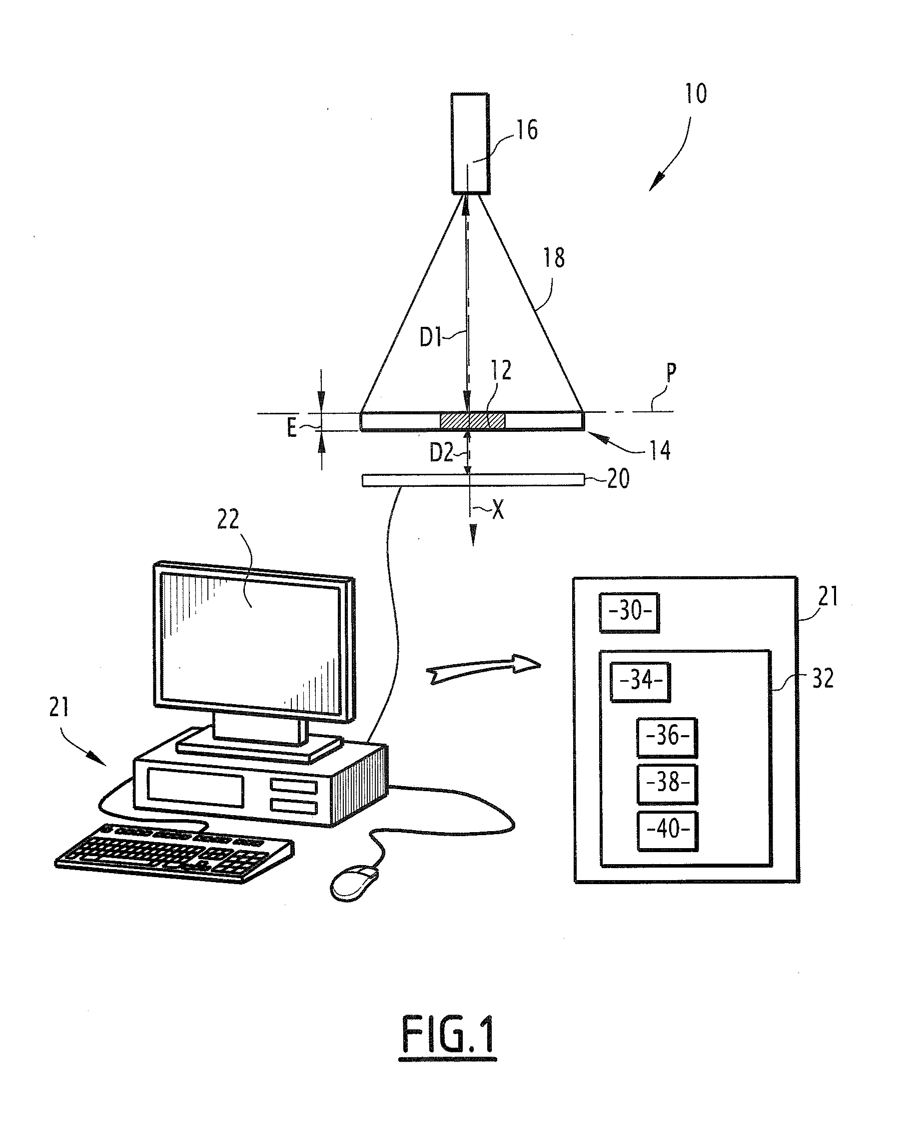
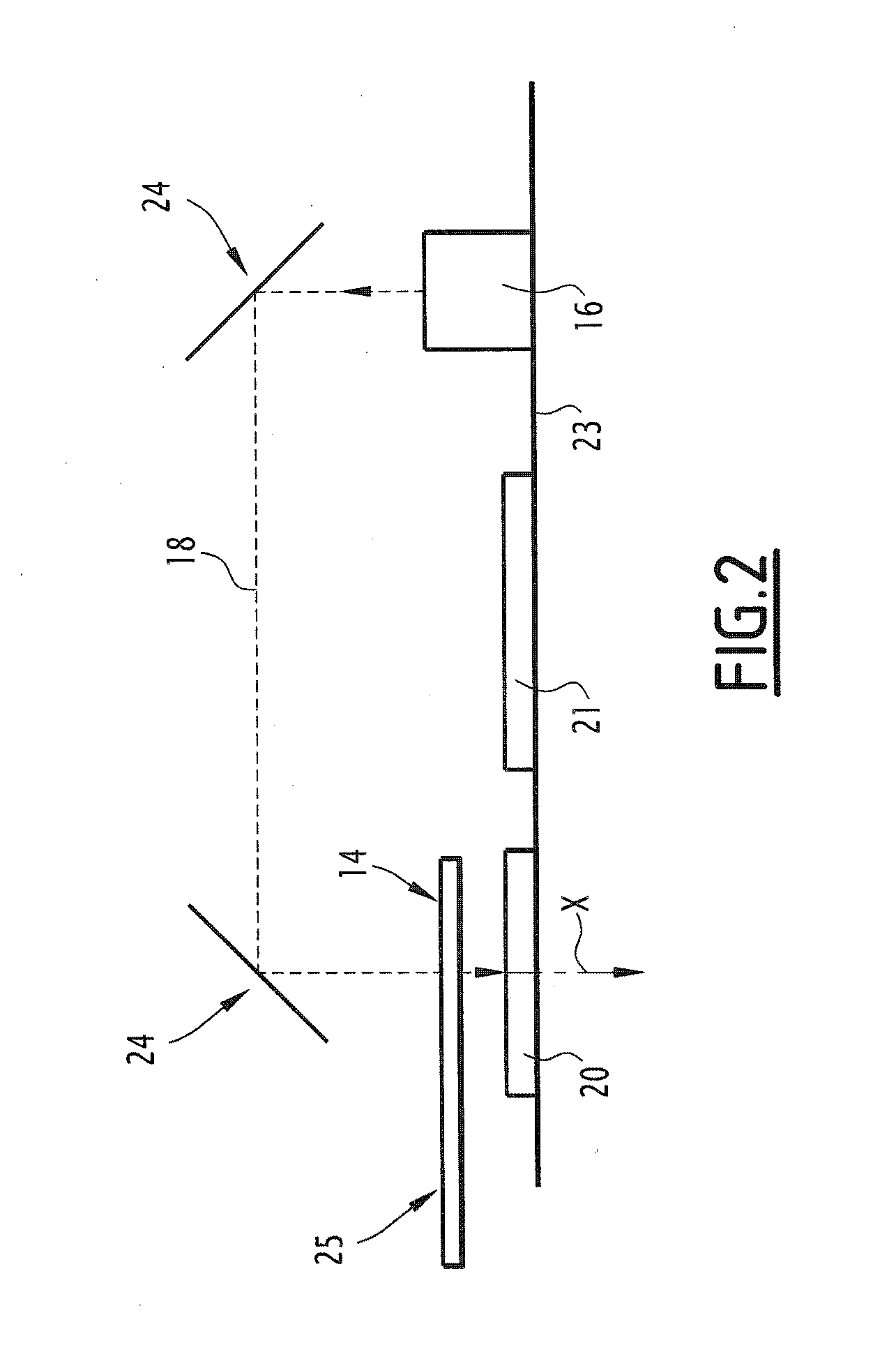
[0160] the characterization system 10 is designed more particularly to characterize the agglomeration of particles contained in a liquid 12. The characterization system 10 is for example capable of characterizing the agglomeration of blood particles, such as red blood cells, also called agglutination of blood particles.

[0161]Information relative to the blood group is then also determined from the agglomeration state, also called agglutination state.

[0162]As known per se, the blood group can be determined using the Beth-Vincent test by detecting the presence of A or B antigens implying the absence of anti-A or anti-B antibodies. In the case where the erythrocytes of the tested blood have an A or B antigen, an antigen-antibody complex will be formed and lead to a cellular aggregation as recalled in table 200, shown in FIG. 12.

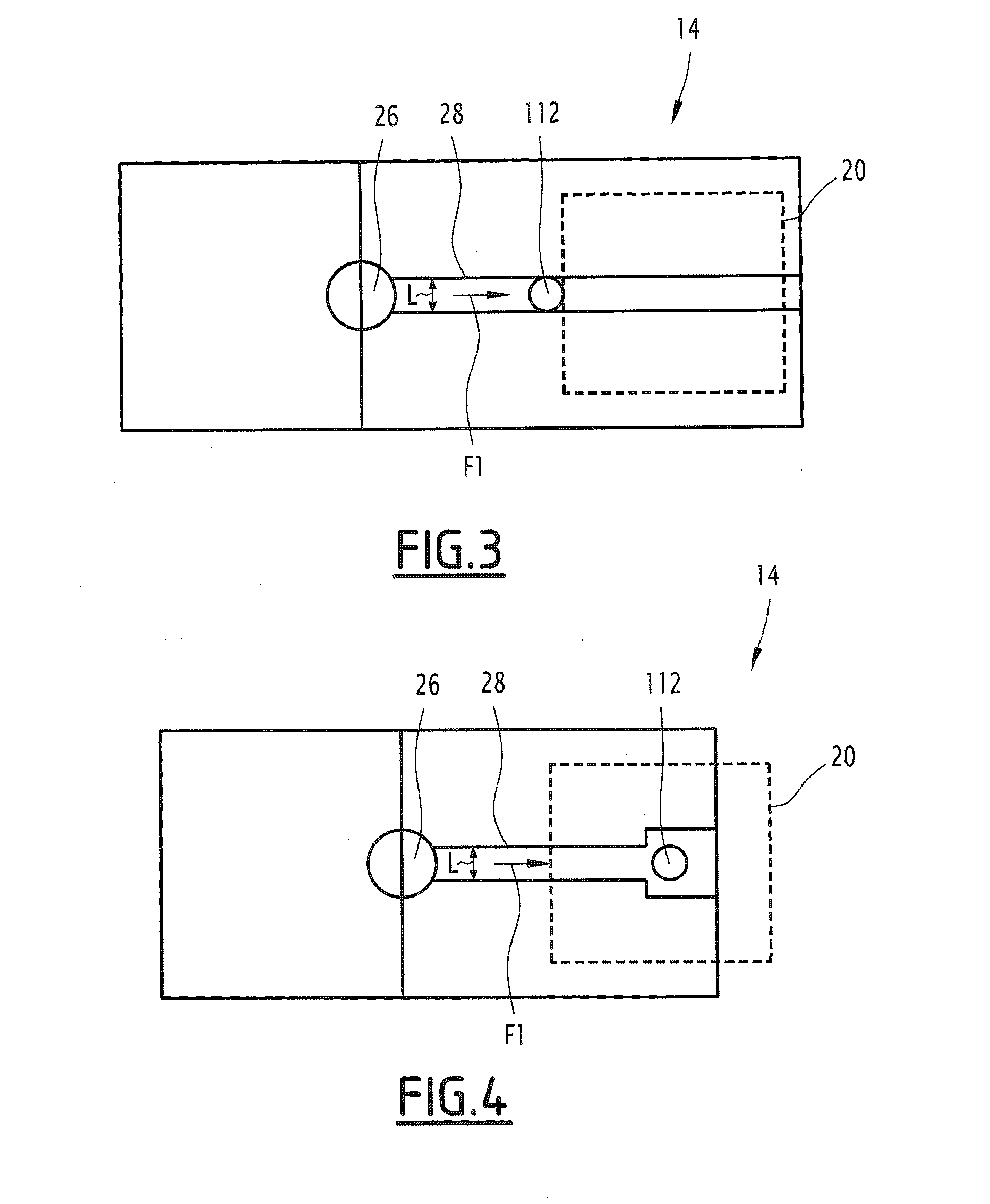
[0163]The fluid chamber 14 includes two separate circulation channels 202, 204, i.e., a first channel 202 and a second channel 204, as shown in FIG. 13.

[0164]Acc...

first embodiment

[0196]As a complement to the first embodiment, the fluid chamber 14 includes a plurality of channels, for example the two channels 202, 204 visible in FIG. 13, so as to characterize the variation of the speed of the particles of the liquid 12 when the liquid 12 is mixed with different reagents, a respective reagent then being positioned in each channel 202, 204 of the fluid chamber 14. This makes it possible, with a same device, to determine different analysis parameters of the same liquid sample, for example the coagulation time and the blood group.

[0197]Such a fluid chamber 14 is for example advantageous to characterize the coagulation of the liquid 12 containing blood, with different reagents capable of favoring the slowing of the blood particles via a coagulation of the blood, such as the different reagents 112 defined above.

[0198]One can see that the characterization system 10 according to the invention makes it possible to observe a larger part of the fluid chamber 14, while h...


PUM

PropertyMeasurementUnit
distanceaaaaaaaaaa
thicknessaaaaaaaaaa
surface areaaaaaaaaaaa

Abstract

The method is provided for characterizing agglomeration of particles in a liquid containing an analyte, including introducing liquid into a fluid chamber; mixing the liquid with a bifunctional reagent, lighting the fluid chamber using an excitation light beam extending through the fluid chamber in a longitudinal direction (X); acquiring at least one image using a matrix photodetector, each image including pixels (In(x,y), x,y representing the coordinates of a pixel of an image, the image (I(x,y)) being formed by radiation transmitted by the lighted fluid chamber; and calculating from at least one acquired image (I(x,y)), at least one indicator (Ind2) characterizing the particle agglomeration. The photodetector can be positioned less than 1 cm from the fluid chamber, and during the calculation step, the calculated indicator (Ind2) is representative of the intensity of the pixels of the image. The method advantageously allows for charactering the agglomeration of particles in a liquid.

Description

CROSS-REFERENCE TO RELATED APPLICATIONS[0001]This application is a divisional application of U.S. patent application Ser. No. 13 / 905,727, filed May 30, 2013, said application hereby incorporated by reference in its entirety.FIELD OF THE INVENTION[0002]The present invention relates to a method for characterizing a variation in the speed of particles or agglomeration of particles, the particles, such as blood particles, being contained in a liquid, the method including the following steps:[0003]introducing the liquid into a fluid chamber;[0004]lighting the fluid chamber using an excitation laser beam emitted by a light source, the laser beam extending through the fluid chamber in a longitudinal direction;[0005]acquiring at least one image using a matrix photodetector, the image being formed by radiation transmitted by the lighted fluid chamber; and[0006]calculating, from at least one acquired image, at least one indicator characterizing the variation of the speed or agglomeration of t...

Claims


Application Information

Patent Timeline
Patent Type & Authority Applications(United States)
IPC IPC(8): G01N33/86G01N33/80G01N21/77G01N15/14
CPCG01N33/86G01N15/1463G01N33/80G01N21/77G01N15/1434G01N2015/1486G01N2015/144G01N2015/0092G01N2015/0073G01N2201/062G01N2201/12G01N2201/06113G01N2021/7769G01N2015/1497G01N33/4905G01N15/1436G01N2015/1454G03H2001/0447G01N2015/012G01N2015/1027G01N21/6452C12M1/3446C12Q1/04C12Q1/56G01N21/253G01N15/0227G01N15/1433G01N15/075G01N2015/018
Inventor POHER, VINCENTCUBIZOLLES, MYRIAM-LAUREPOUTEAU, PATRICKALLIER, CEDRICSPIACZKA, JOHANNA
Owner COMMISSARIAT A LENERGIE ATOMIQUE ET AUX ENERGIES ALTERNATIVES
Learn More