Metering module for metering a reducing agent

a technology of reducing agent and metering module, which is applied in the direction of machines/engines, mechanical apparatus, engine components, etc., can solve the problems of limiting the maximum admissible temperature of the metering module, affecting the operation affecting the functionality of the dosing unit, so as to reduce the manufacturing cost and construction weight, reduce the manufacturing cost, and reduce the manufacturing cos

Active Publication Date: 2016-10-20
ROBERT BOSCH GMBH
View PDF8 Cites 19 Cited by
  • Summary
  • Abstract
  • Description
  • Claims
  • Application Information

AI Technical Summary

Benefits of technology

[0015]By way of the solution proposed according to the invention, of the dosing device having an injection valve and having a receiving device connected thereto to form a structural unit by way of cohesive connections, optimum protection with respect to external media, for example spray water, is achieved. Simple structural measures and reduced manufacturing outlay for the receiving device, comprising a cooling body element and a cover element, reduce the manufacturing costs and the weight of the construction.
[0016]For the injection valve, which is cooled in optimized fashion, increased robustness with respect to temperature loads is realized. In particular, because the reducing agent that is introduced into the exhaust pipe by the injection valve changes into the vapor phase in the presence of a temperature higher than 140° C. to 160° C., it is possible, with an improved dissipation of heat, to prevent boiling within the injection valve. Owing to the improved cooling of the injection valve in combination with insulation with respect to the surroundings, the arrangement of the dosing device for a reducing agent can be optimized.
[0017]The connection of the injection valve to the receiving device by way of cohesive welded connections offers optimum sealing without the use of additional seals, which are problematic with regard to their temperature stability.
[0018]Further advantages include the fact that the receiving device, and / or the cooling body element and the cover element, can be manufactured from thin metal sheets, whereby a weight saving and simple manufacturing are possible. Furthermore, the cooling body element can, by way of dividing elements, be designed optimally for the throughflow of a cooling medium.
[0019]Furthermore, the mounting of the injection valve, and the compensation of expansions induced by temperature changes in the dosing device according to the invention, can be made possible in a simple manner. In accordance with the solution proposed according to the invention, the injection valve is virtually completely surrounded by the cooling medium. The cooling medium jacket surrounding the injection valve as a thermal barrier is virtually complete in a radial direction. With the solution proposed according to the invention, it can furthermore be achieved that the injection valve can be installed in optimum fashion in a manner dependent on its installation location and its operating conditions. In a manner dependent on whether the injection valve is used at an installation location exposed to high temperatures or at a location which is sensitive with regard to acoustics, it is possible to realize an appropriate attachment of the injection valve in optimum fashion in a receiving device for the injection valve. With regard to a temperature-resistant installation location, improved heat dissipation can be allowed for through the selection of suitable materials and of a suitable temperature level of the cooling medium. By contrast, if the injection valve is used in an acoustically sensitive location, then by way of correspondingly optimized installation, sound propagation in the receiving device of the injection valve can be realized without the provision of sound transmission bridges.

Problems solved by technology

Owing to this inevitably high introduction of heat into the dosing module, there is the risk of overheating of the materials, for example of those used for insulators and seals, which permanently impairs the functionality of the dosing unit.
The use of elastomers for sealing, mounting and / or insulation limits the maximum admissible temperature of the dosing module.

Method used


Image

  • Metering module for metering a reducing agent
  • Metering module for metering a reducing agent
  • Metering module for metering a reducing agent

Examples


Embodiment Construction

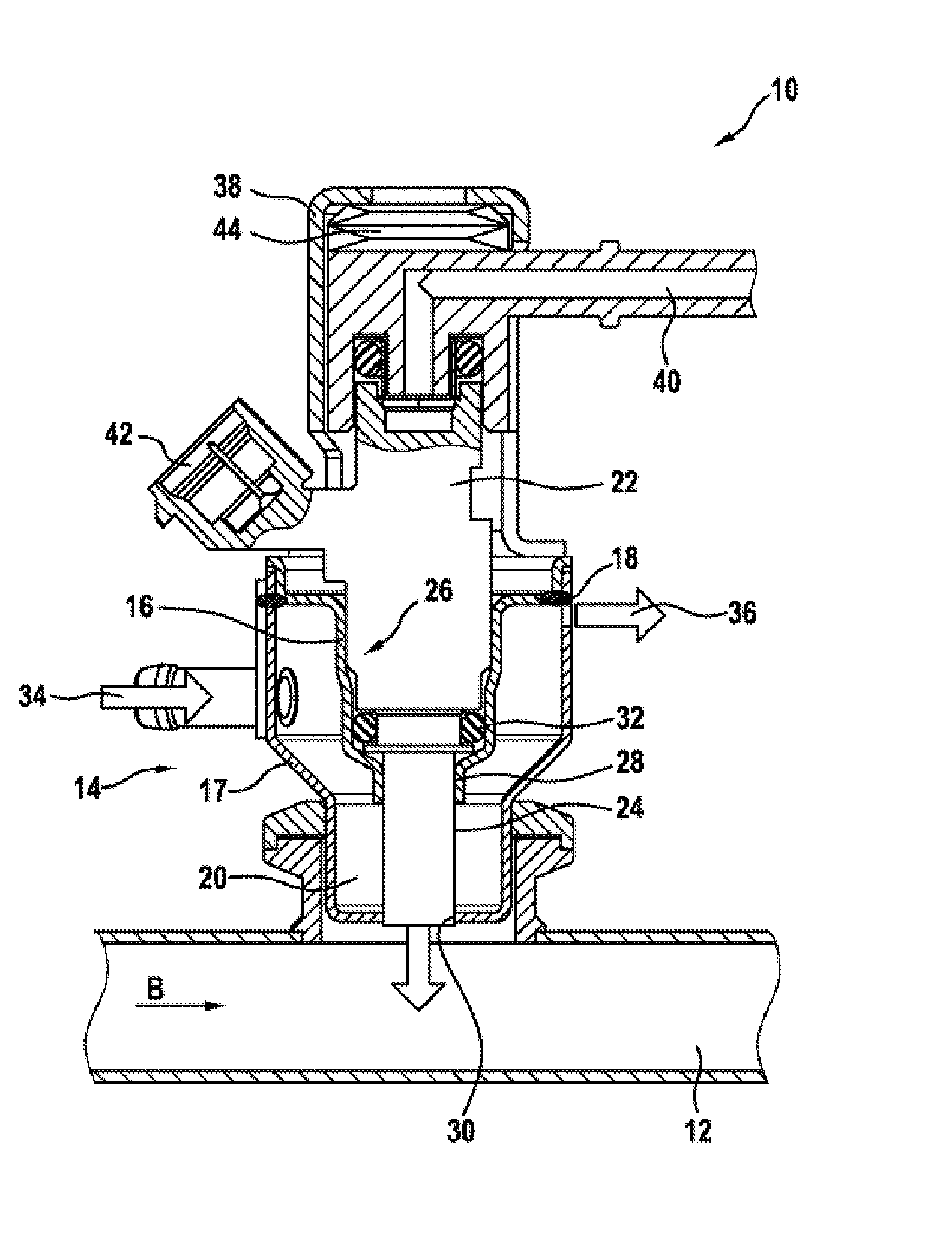
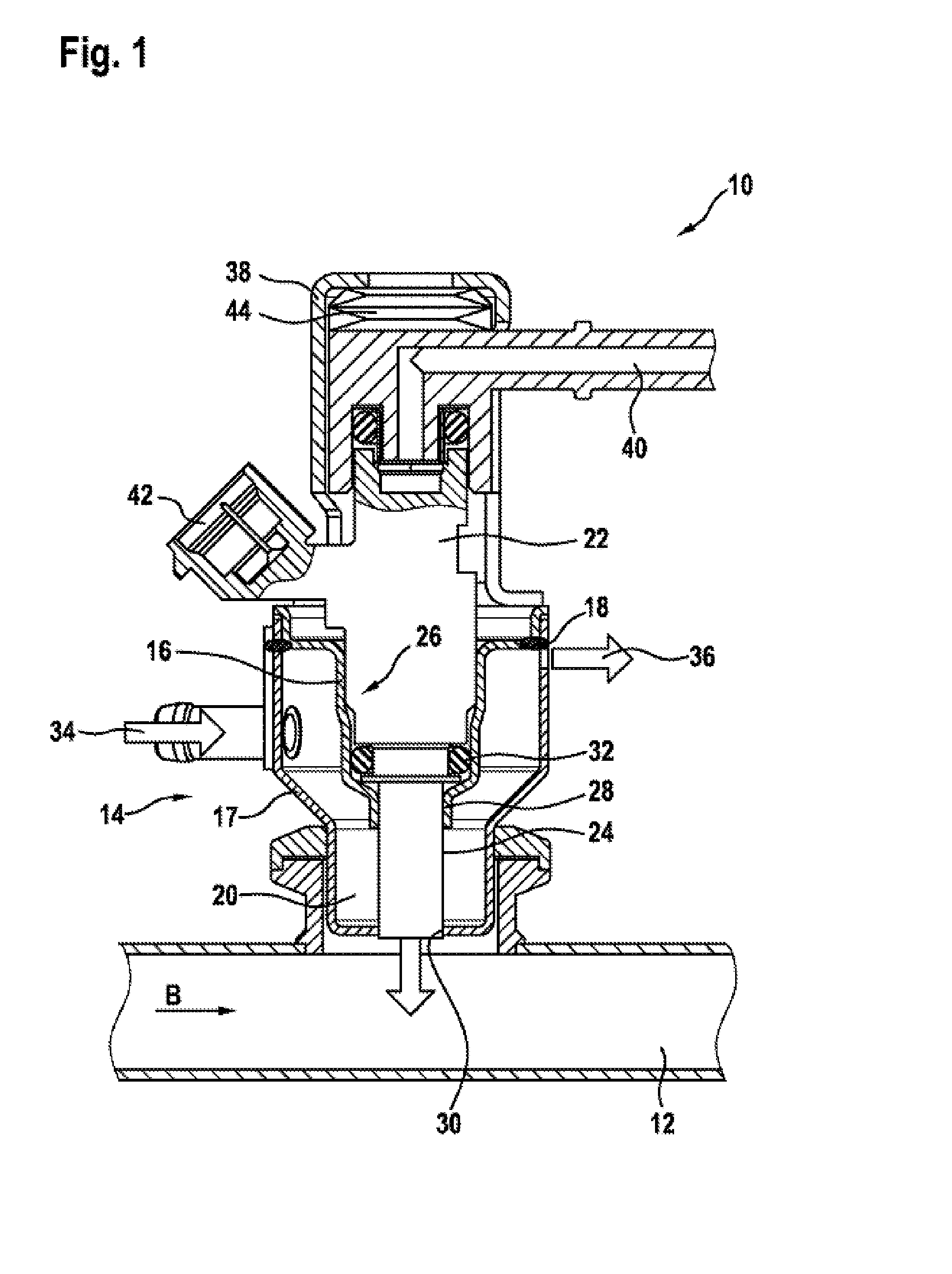
[0024]FIG. 1 shows a dosing device 10 for use in SCR systems for the dosing of reducing agent into an exhaust pipe 12, wherein an exhaust-gas flow passes through the exhaust pipe 12 in a flow direction B. The exhaust-gas flow originates from an internal combustion engine which is not illustrated in FIG. 1 and to which, at the outlet side, the exhaust pipe 12 is connected. The dosing device 10 comprises a main body 14 which is formed from a first metal sheet 16 and from a second metal sheet 17, which are connected to one another in an abutment region or an overlap region by way of a brazed connection 18. The metal sheets 16 and 17 are spaced apart from one another and form a ring-shaped chamber 20. Furthermore, in the main body 14, there is received an injection valve 22, the housing of which is denoted by 24. The contour of the first metal sheet 16 is in this case selected such that a matching receptacle 26 for the injection valve 22 is formed. The injection valve 22 forms, with the...


PUM


Abstract

The invention relates to a metering device (10) for introducing a process liquid or auxiliary agent into a flow pipe of an internal combustion engine, in particular for introducing a reducing agent into an exhaust gas pipe (12). Said device comprises an injection valve (22) and a receiving device (50) comprising a heat sink element (46) and a cover element (48). The injection valve (22) and the receiving device (50) are combined to form a structural unit by means of bonded connections (62, 64).

Description

BACKGROUND OF THE INVENTION[0001]The invention relates to a dosing device, comprising an injection valve and a receiving device which are combined to form a structural unit by way of cohesive connections.[0002]In known dosing devices for liquid reducing agents, such as are known for example from DE 10 2008 041 486, a dosing module is used which comprises a dosing unit, for example a dosing valve, for the injection of a reducing agent into the exhaust-gas region and which is held by a holding device or an adapter by means of which a connection to the exhaust tract is realized. To be able to introduce the reducing agent into the exhaust gas in an optimum manner, the dosing module must be positioned as close as possible to the hot exhaust tract, wherein maximum temperatures of 700° C. are reached in the exhaust tract of internal combustion engines. Owing to this inevitably high introduction of heat into the dosing module, there is the risk of overheating of the materials, for example o...

Claims


Application Information

Patent Timeline
Patent Type & Authority Applications(United States)
IPC IPC(8): F01N3/20
CPCF01N3/2066F01N2450/22F01N2610/1453F01N2610/11F01N2610/02F01N2610/00Y02T10/12
Inventor MURST, MARTINKNITTEL, ACHIMKREHER, THILORANKEL, THORSTENWINKLER, JOCHENHENKEL, CLAUDIUSELSOE, GELLERT
Owner ROBERT BOSCH GMBH
Why Eureka
Try Eureka