Magnet Manufacturing Method And Magnet

a manufacturing method and magnet technology, applied in the field of magnet manufacturing methods and magnets, can solve the problems of reduced residual magnetic flux density, difficult sintering, and reduced magnet density, and achieve the effect of high residual magnetic flux density

Inactive Publication Date: 2016-10-20
JTEKT CORP
View PDF3 Cites 4 Cited by
  • Summary
  • Abstract
  • Description
  • Claims
  • Application Information

AI Technical Summary

Benefits of technology

[0013]An object of the invention is to provide a magnet manufacturing method and a magnet that allow a high residual magnetic flux density to be obtained without the use of a bond.

Problems solved by technology

When the Sm—Fe—N alloy is used, sintering is difficult due to the low decomposition temperature of the Sm—Fe—N alloy.
However, the use of the bond such as resin reduces the density of the magnet, causing a reduction in residual magnetic flux density.
However, for magnets, there has been a demand to further enhance the residual magnetic flux density, and the enhancement of this characteristic is limited because a large amount of lubricant remains which does not contribute to magnetic characteristics.

Method used


Image

  • Magnet Manufacturing Method And Magnet
  • Magnet Manufacturing Method And Magnet
  • Magnet Manufacturing Method And Magnet

Examples


Embodiment Construction

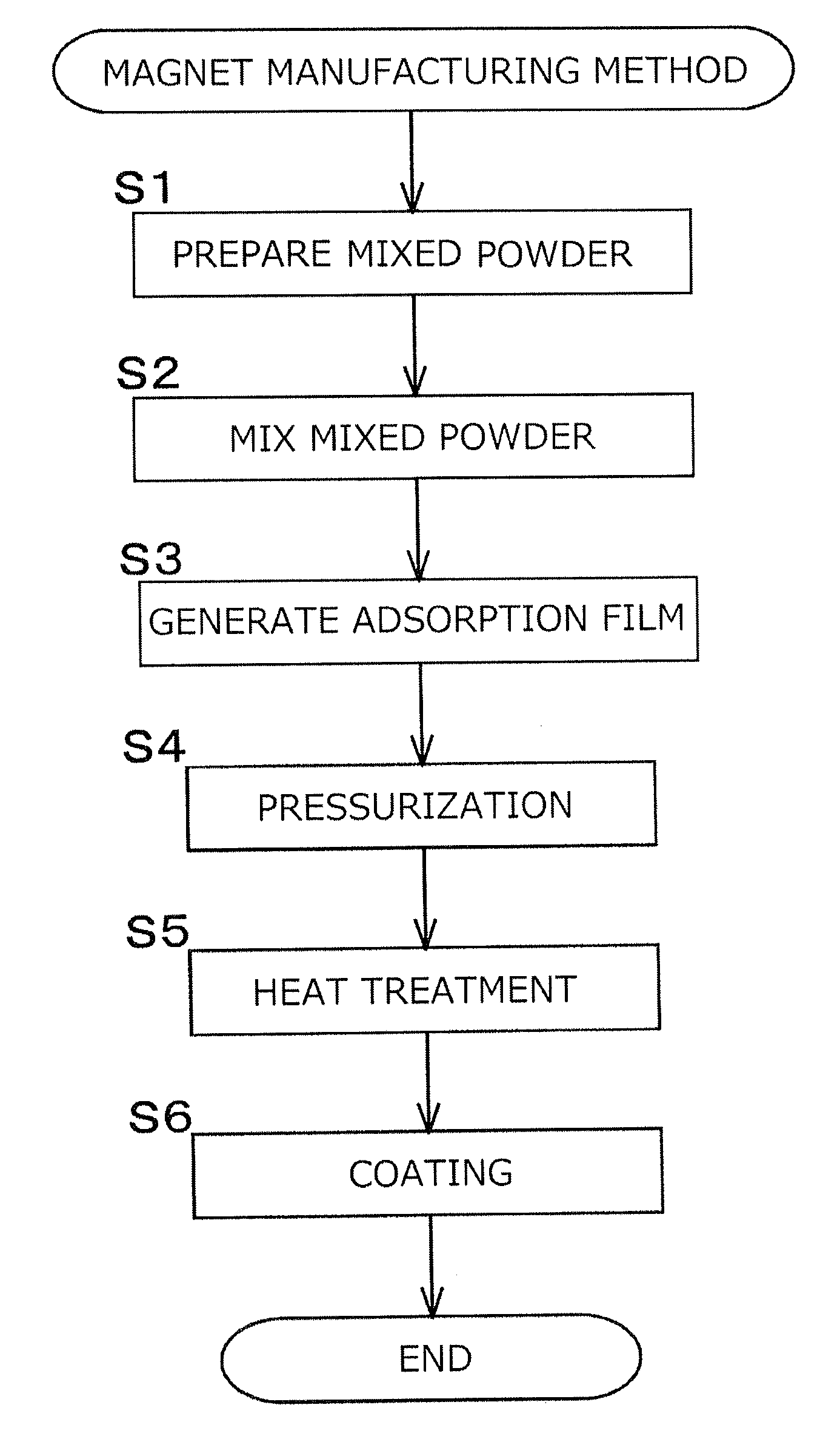
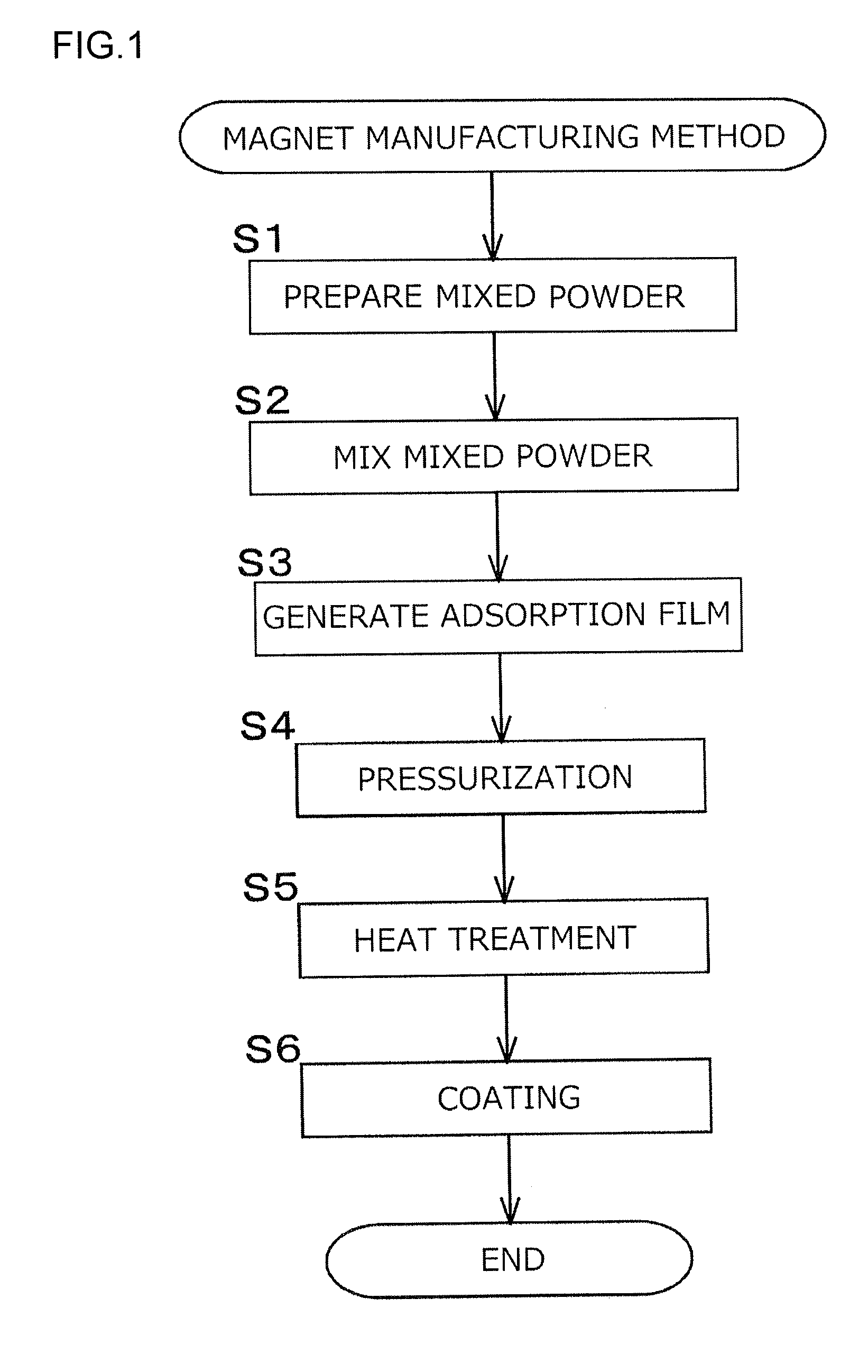
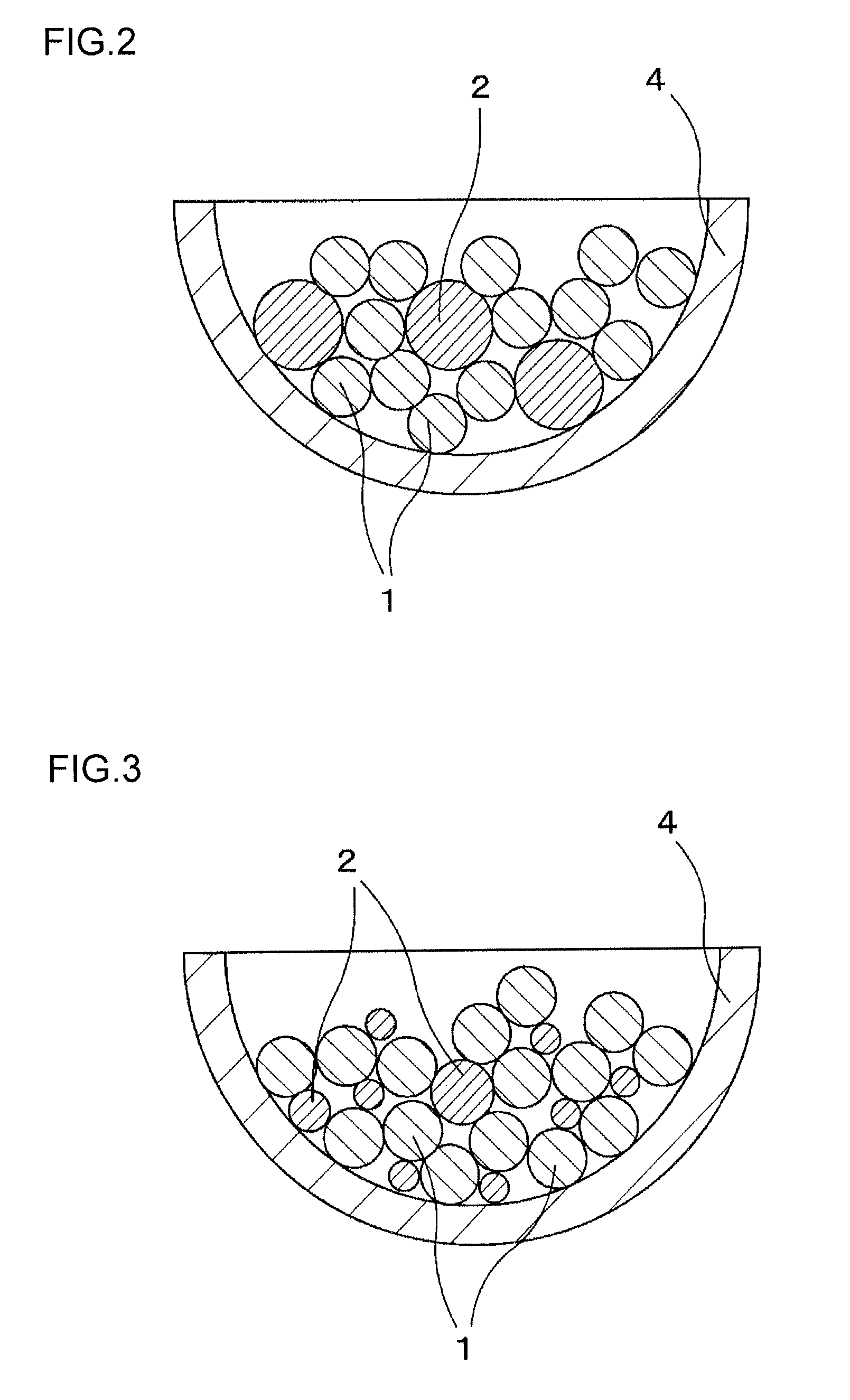
[0033]A magnet manufacturing method according to the invention will be described as an embodiment with reference to FIGS. 1 to 10. FIG. 1 is a diagram illustrating steps of the magnet manufacturing method of a first embodiment.

[0034]As illustrated in step S1 in FIG. 1, mixed powder is prepared which contains magnetic powder 1 of a hard magnetic material as a raw material for a magnet and a lubricant 2 that allows formation of an adsorption film on a surface of the magnetic powder 1.

[0035]As the magnetic powder 1, a compound is used which includes one or more of an Fe—N-based compound and an R—Fe—N-based compound. A rare earth element represented by R is preferably an element that is known as a so-called rare earth element and that is other than Dy. In particular, light rare earth elements are preferable, and among the light rare earth elements, Sm is suitable. The light rare earth elements described herein refer to elements included in lanthanoids and having a smaller atomic weight ...


PUM

PropertyMeasurementUnit
particle sizeaaaaaaaaaa
specific gravityaaaaaaaaaa

Abstract

A magnet manufacturing method has a step of preparing mixed powder of magnetic powder of a hard magnetic material, which includes one or more of an Fe—N-based compound and an R—Fe—N-based compound and a lubricant that allows formation of an adsorption film on a surface of the magnetic powder, a step of heating the mixed powder at a temperature that is equal to or higher than a melting point of the lubricant and that is lower than a decomposition temperature of the magnetic powder to form the adsorption film of the lubricant on the surface of the magnetic powder, a step of pressurizing and molding the magnetic powder in order to obtain a primary molding, and a step of heating the primary molding at a temperature that is lower than the decomposition temperature of the magnetic powder.

Description

INCORPORATION BY REFERENCE[0001]The disclosure of Japanese Patent Application No. 2015-084010 filed on Apr. 16, 2015 including the specification, drawings and abstract, is incorporated herein by reference in its entirety.BACKGROUND OF THE INVENTION[0002]1. Field of the Invention[0003]The invention relates to a magnet manufacturing method and a magnet.[0004]2. Description of Related Art[0005]Japanese Patent Application Publication No. 2007-39794 (JP 2007-39794 A) describes a magnet containing an Nd—Fe—B alloy or an Sm—Fe—N alloy. JP 2007-39794 further discloses that a soft magnetic metal is mixed with the above-described alloy and that the mixture is molded under pressure and sintered.[0006]Japanese Patent Application Publication No. 2012-69962 (JP 2012-69962 A) discloses that an R—Fe—N—H-based magnetic material and soft magnetic powder are mixed together and that the mixture is compacted and solidified by impact compression using an underwater shock wave and that after the impact co...

Claims


Application Information

Patent Timeline
Patent Type & Authority Applications(United States)
IPC IPC(8): H01F41/02H01F1/053B22F5/00B22F1/00B22F3/16H01F1/08C22C38/00B22F1/10B22F1/102
CPCH01F41/0266H01F1/08H01F1/053C22C38/005C22C38/001B22F2998/10B22F3/16B22F5/00B22F2301/355B22F2302/20B22F1/0062H01F1/0551H01F1/0556B22F1/10B22F1/102H01F1/059H01F1/06
Inventor MIO, TAKUMINISHI, KOJIKIMOTO, YUSUKETAMURA, TAKASHI
Owner JTEKT CORP
Why Eureka
Try Eureka