Robot apparatus and method for controlling robot apparatus

a robot and robot technology, applied in the field of robot apparatus, can solve the problems of inability to achieve a sufficient precision range, the reactive force becomes an extremely large disturbance, and the member cannot, and achieve the effect of high precision, high precision and light weigh

Active Publication Date: 2016-10-27
CANON KK
View PDF4 Cites 9 Cited by
  • Summary
  • Abstract
  • Description
  • Claims
  • Application Information

AI Technical Summary

Benefits of technology

[0020]The robot apparatus according to the present invention determines a reactive force of a wire member, which is applied to a joint when the wire member that transmits a driving signal therethrough is deformed, by a sensor, and drives and controls the above-described driving source that drives the joint, based on the determined value of the reactive force. Thereby, the robot apparatus can measure or estimate a force, for instance, occurring in the joint thereof with high precision, and can control the joint of the robot apparatus with high precision. For instance, when controlling a torque (force) to be applied to a work or a link by using the sensor for determining the torque, the robot apparatus can perform a computation of removing the reactive force of the wire member, which acts as the disturbance, from the output of the sensor for determining the torque, and the like, and can precisely control the torque (force), based on a precise torque detection. Thereby, for instance, the robot apparatus having a general-purpose structure can precisely control the force of the joint, and can achieve the assembly of a component having a small weight of approximately several grams. For this reason, the robot apparatus having the general-purpose structure can be used in a production line which assembles the component having the very light weight, does not need the dedicated apparatus, a manual operation by human power and the like, can reduce the design and the manufacture cost of the dedicated apparatus, and can reduce a manufacturing period. In addition, the robot apparatus can reduce a start-up cost of a production line of assembling the minute components.

Problems solved by technology

One of the reasons is in such a point that the present multi-joint robot does not control the force (torque) with so high precision, and still cannot attain a sufficient precision range to carry out an assembly of such a range that a load which an end effector of the front end of the robot arm exerts on a component is approximately several grams.
However, the reactive force which is generated by the deformation of the wire member that transmits the driving signal to the above-described joint (and / or end effector) which is associated with the operation of the robot apparatus gives influence on a measured value of the torque sensor that is arranged in the joint, as a measurement error.
Accordingly, when the force (or torque) is controlled with a precision of several grams, there are problems that such a reactive force becomes an extremely large disturbance, and gives influence on the precision of the control.
Secondly, the wire member cannot be always arranged in the state equivalent to that in the preliminary measurement, and the same reactive force is not actually generated by the same joint action as in the preliminary measurement, because of such a problem of installation precision.
Accordingly, in the technology of Japanese Patent Application Laid-Open No. 2012-218104, the reactive force of the wire member is considered in the control, but still there is a problem that the force (torque) cannot be controlled with sufficient precision.
However, in the control for the force (torque) particularly of the order of several grams as has been described above, even the technology in Japanese Patent Application Laid-Open No. 2012-218104 cannot attain a sufficient precision, and there is a possibility of showing lowered force controllability.
Then, a circumstance that the dedicated apparatus as described above becomes separately necessary for each of tiny (minute) components can become a significant bottleneck in regard to the achievement of the manufacturing of the wide variety of products in small quantities.
If a large number of the tiny (minute) components necessary for the manufacturing of the wide variety of products in small quantities each need the design and manufacture of the above-described dedicated apparatus, such problems possibly occur that a start-up period of a production line is prolonged and a start-up cost increases, because of the necessity.

Method used


Image

  • Robot apparatus and method for controlling robot apparatus
  • Robot apparatus and method for controlling robot apparatus
  • Robot apparatus and method for controlling robot apparatus

Examples


exemplary embodiment 1

[0032](Basic Structure of Robot Apparatus)

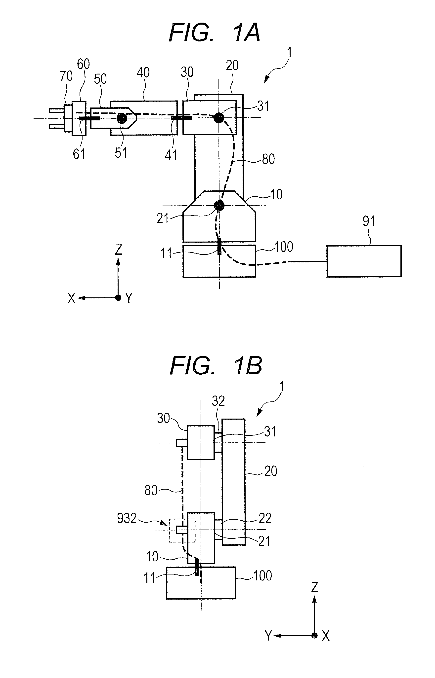
[0033]FIG. 1A and FIG. 1B are views illustrating a whole structure of a multi-joint robot apparatus, as one example of a robot apparatus which has adopted the present invention. FIG. 1A is a view illustrating the robot apparatus of the present exemplary embodiment which is viewed, for instance, from a side face. FIG. 1A illustrates coordinates of a three-dimensional (XYZ) coordinate system which is used for control of this robot apparatus, in the lower left part thereof. As is illustrated in FIG. 1A, a Z-axis among these coordinates is arranged so as to point upward in FIG. 1A, and an X-axis is arranged so as to point the left direction in FIG. 1A. FIG. 1B is a view illustrating a robot arm 1 of the robot apparatus of the present exemplary embodiment, which is viewed, for instance, from the rear part (left part in FIG. 1A). FIG. 1B illustrates also similar coordinates of the three-dimensional (XYZ) coordinate system, in the lower right part ...

exemplary embodiment 2

[0098]As for the cable reactive force measuring unit which is arranged on the rotational joint of the robot arm 1, a different structure is considered. Also in the present exemplary embodiment, the configuration of the control system of the robot apparatus shall be similar to that illustrated in FIG. 4 and FIG. 9 in the above-described Exemplary Embodiment 1. In addition, in the present exemplary embodiment and an exemplary embodiment which will be described later, the members which are same as or equivalent to those in the above-described Exemplary Embodiment 1 are designated by the same (or similar) reference characteristics below, and the detailed description will be omitted.

[0099](Arrangement of Force Sensor)

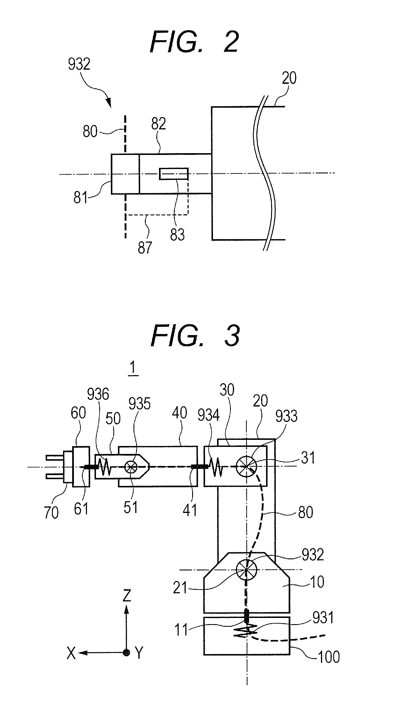
[0100]FIG. 5 illustrates the structure of the robot arm 1, and the cable reactive force measuring units 931 to 936 which are arranged on the respective rotational joints 11, 21, 31, 41, 51 and 61, in the present exemplary embodiment.

[0101]In the present exemplary embodiment,...

exemplary embodiment 3

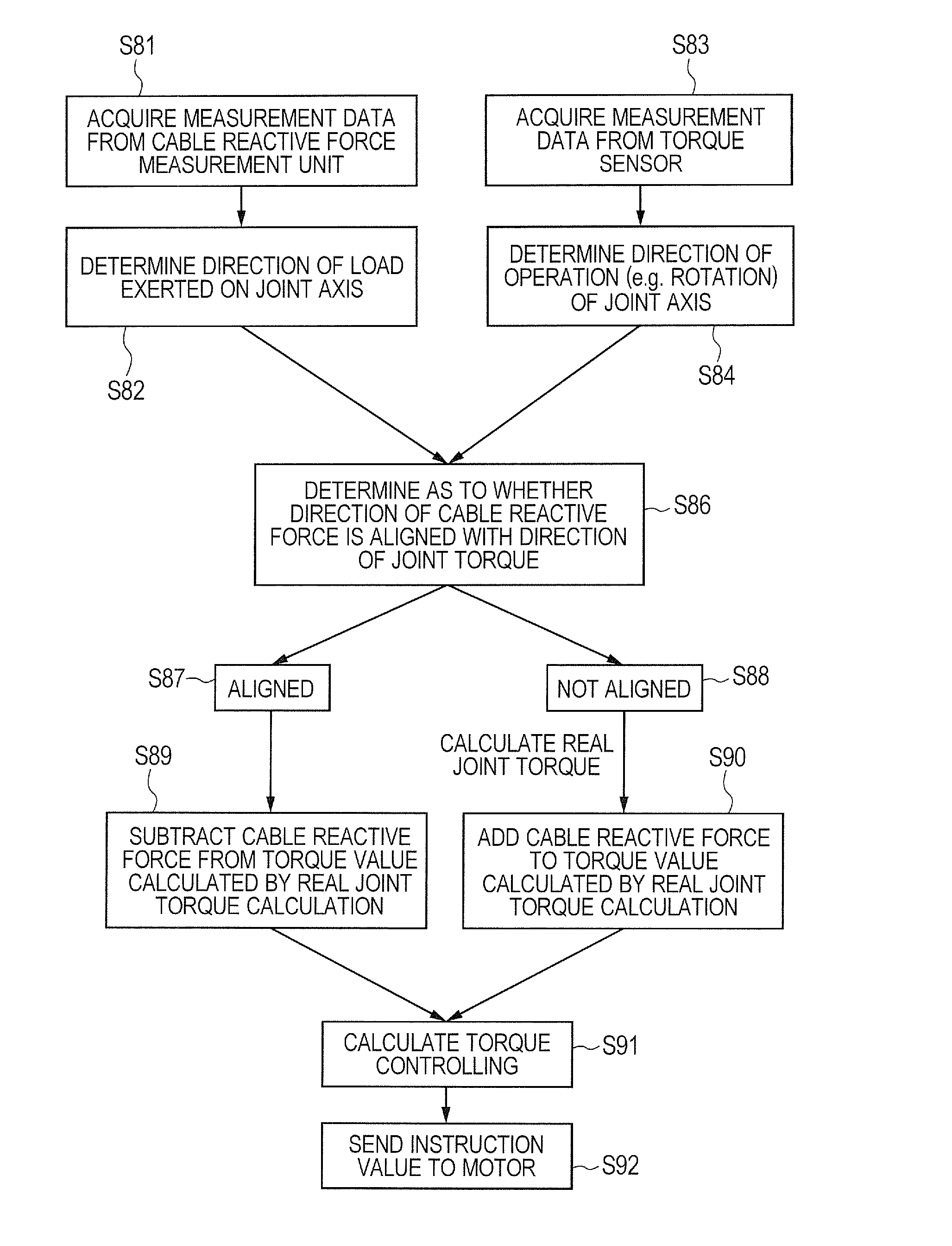
[0115]In the present exemplary embodiment, some examples of a robot control procedure (robot control program) are illustrated which can be executed by the CPU 601 of the above-described controlling apparatus 91. FIG. 7 and FIG. 8 illustrate a flow of the robot control procedure (robot control program) which can be executed by the CPU 601 of the controlling apparatus 91. A control example in FIG. 7 is an example of correcting instruction values for driving the rotational joints sent from the instruction apparatus 94, according to the cable reactive forces which have been measured by the cable reactive force measuring units 931, 932, 933, 934, 935 and 936. In addition, the control example in FIG. 8 is an example of correcting the torque control which feeds back the output values of the torque sensors 12, 22, 32, 42, 52 and 62, according to the cable reactive forces which have been measured by the cable reactive force measuring units 931, 932, 933, 934, 935 and 936. The controls in FIG...


PUM


Abstract

A robot apparatus determines a reactive force of a wire member by a sensor, used for the transmission of a driving signal between the robot apparatus and a joint (or end effector). The robot apparatus includes: a plurality of links which constitute a robot arm; rotational joints which connect each of the links to each other; a motor which drives each of the rotational joints; and a cable as a wire member, which is arranged along each link and transmits a driving signal at least to a driving source. A controlling apparatus drives and controls the motor which drives the rotational joints, based on a value of a reactive force, which a cable reactive force measuring unit outputs, which measures the reactive force to be applied to a joint portion when the cable is deformed.

Description

BACKGROUND OF THE INVENTION[0001]1. Field of the Invention[0002]The present invention relates to a robot apparatus in which a wire member that transmits a driving signal and / or a control signal to each unit of a robot arm therethrough is arranged along a plurality of links which constitute a robot arm; and a method for controlling the same.[0003]2. Description of the Related Art[0004]In recent years, in a robot apparatus, for instance, in a multi-axis and multi-joint robot in which a joint is rotated and constrained, a multi-joint robot has received attention which arranges a torque sensor for measuring a torque that a driving source exerts on a link, in a joint, and controls the torque (force) which occurs in the joint. By arranging the torque sensor in the joint, it has become easy for the multi-joint robot to control the force occurring in the joint thereof and to control a load and / or a force which an end effector arranged in the front end of the robot arm exerts on a component....

Claims


Application Information

Patent Timeline
Patent Type & Authority Applications(United States)
IPC IPC(8): B25J9/16B25J13/08
CPCB25J13/085B25J9/1633B25J19/0025B25J9/1694G05B2219/40599
Inventor OGAWARA, TAKAYUKI
Owner CANON KK
Why Eureka
Try Eureka