
Fluid Treatment Tank Having a Distributor Plate

Active Publication Date: 2016-10-27
CLACK CORP
View PDF0 Cites 1 Cited by
  • Summary
  • Abstract
  • Description
  • Claims
  • Application Information

AI Technical Summary

Benefits of technology

The invention is a fluid treatment tank with a two-part distributor plate that allows for precise and accurate fluid treatment features. The tank liner is made from blow-molded HDPE, and the distributor plate is made from thermoplastic materials which have low shrink rate variability. The tank liner is attached to the tank using a thermally bonded ring and the distributor plate is mounted on the tank's cylindrical wall. The method includes attaching the ring to the cylindrical wall and mounting the disk on the ring while inhibiting axial movement of the disk. The distributor plate has high and low shrink rate variability thermoplastic materials with precise tolerances for injection-molding fine features. The tank also includes an annular flange and engagement surface for secure attachment of the inner disk. The technical effects of the invention include improved fluid treatment accuracy, reduced shrinkage variation, and precise attachment of the tank liner to the tank.

Problems solved by technology

HDPE is easy to injection-mold into virtually any desired shape, but experiences relatively low dimensional stability because it has a relatively high “shrink rate.” The shrink rate or “shrinkage ratio” is a measurement of shrinkage occurring when a molten polymer cooling in a mold contracts as its temperature drops.
The low dimensional stability exhibited by HDPE can hinder the injection molding of relatively fine distributor plate features such as slots.
The relatively high shrink rate of HDPE and resultant low dimensional stability can lead to significant variations of slot width between slots and even within slots in a molded distributor plate.
Hence, it is usually difficult or impossible to maintain close tolerances of fine features molded from a material having a high shrink rate.
High shrink rate variation also hinders precision molding fine features.
However, such compensation is difficult or impossible for materials having a low “dimensional predictability” or dimensional stability on a highly repeatable basis due to its high “heat shrink rate variability.” The “heat shrink rate variability” of a material is defined herein as the difference between highest shrink rate and the lowest shrink rate of that material as measured in accordance with an industry accepted standard such as ASTM D955.
For example, HDPE has such a high shrink rate variability (on the order of + / −2.5%) that it is difficult, if not impossible, to adequately predict for shrinkage when designing the mold and the molding process properties to prevent undesired variations in slot width, shape, and / or orientation.

Method used


Image

  • Fluid Treatment Tank Having a Distributor Plate
  • Fluid Treatment Tank Having a Distributor Plate
  • Fluid Treatment Tank Having a Distributor Plate

Examples


Embodiment Construction

[0025]Distributor plates constructed in accordance with the invention could be used in a variety of tanks configured to treat a variety of fluids using any of a number of media. Hence, while preferred embodiments of the invention now will be described in conjunction with a resin tank of a water treatment system, it is to be understood that the invention is not so limited.

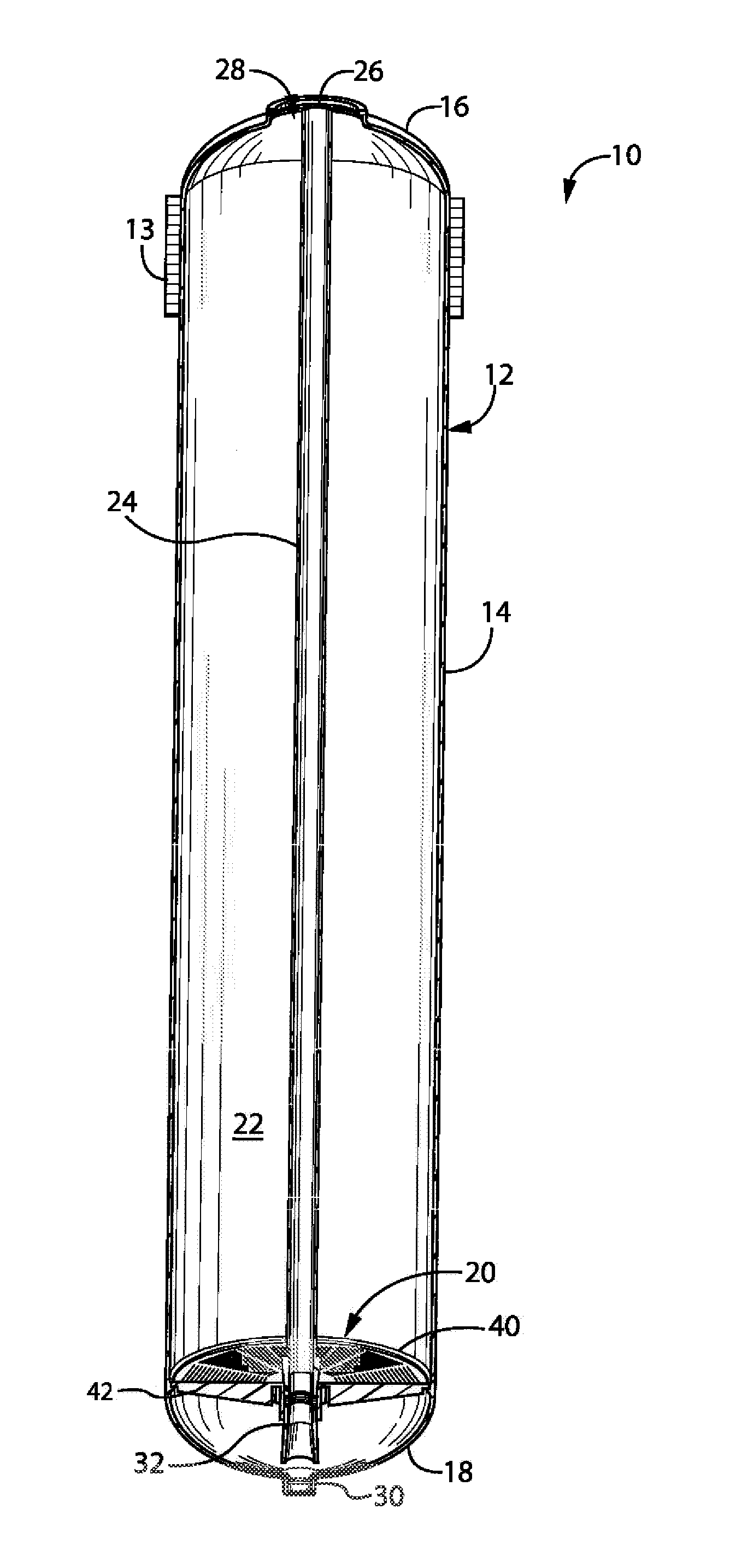
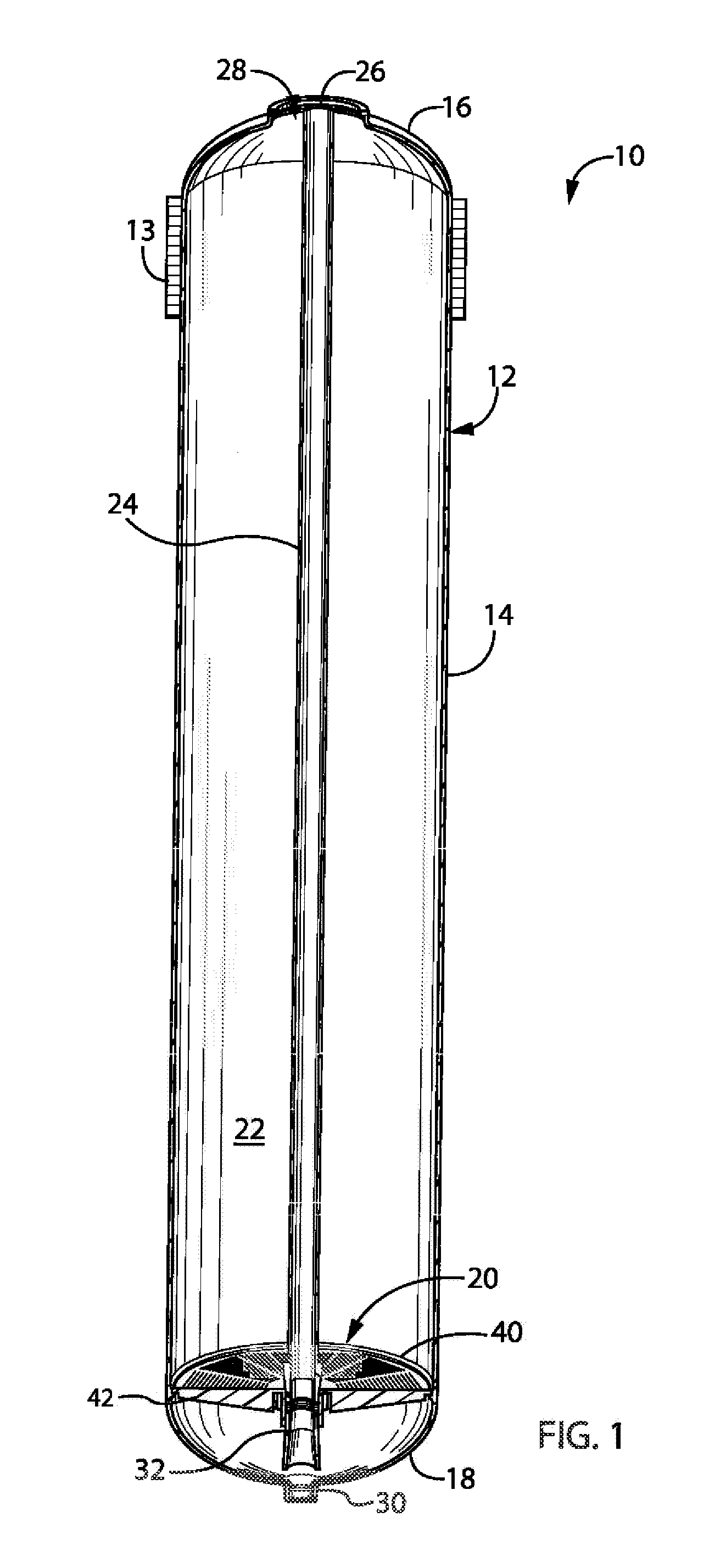
[0026]Referring now to the drawings and, initially, FIG. 1, a resin tank 10 includes a tank liner 12 reinforced with wound fiberglass 13 (only a portion of which is shown in FIG. 1). One of variety of water treatment systems with which the resin tank 10 is usable is disclosed in U.S. Pat. No. 6,402,944, the contents which are incorporated herein by reference.

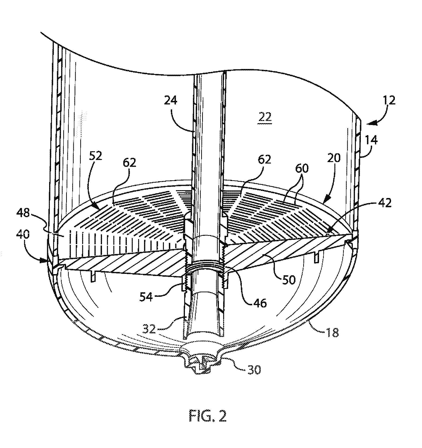
[0027]The tank liner 12 is made of a thermoplastic material such as blow-molded high-density polyethylene (HDPE). Liner 12 includes a generally cylindrical hollow body or wall 14 and upper and lower generally semi-spherical top and bottom ends 16 and 18. A featu...


PUM

PropertyMeasurementUnit
Fractionaaaaaaaaaa
Shrinkageaaaaaaaaaa
Shrinkageaaaaaaaaaa

Abstract

A distributor plate for a fluid tank such as a water softener pressure vessel separates the resin bed from a lower end of the resin tank. The distributor plate includes an outer ring that is affixed to the wall of the tank and that is formed of a first thermoplastic material having a relatively low dimensional predictability, and an inner disk that is supported on the outer ring and that is formed from a second thermoplastic material having a relatively high dimensional predictability when compared to that of the first thermoplastic material, the inner disk being fluid permeable but fluid treatment media impermeable. The outer ring and inner disk may be made from high density polyethylene (HDPE) and unfilled or 30% glass-filled Noryl®, respectively. Also disclosed is a method of assembling a pressure vessel.

Description

CROSS REFERENCE TO A RELATED APPLICATION[0001]This application claims priority under 35 USC §1.119(e) to earlier U.S. Provisional Patent Application Ser. No. 62 / 151,022, filed Apr. 22, 2015 and entitled DISTRIBUTOR ARRANGEMENT FOR A FLUID TREATMENT TANK, the contents of which are incorporated by reference in their entirety.BACKGROUND OF THE INVENTION[0002]1. Field of the Invention[0003]The invention generally relates to fluid treatment tanks and, more particularly, to a tank that has a fluid-permeable distributor plate and that can be easily manufactured and assembled with high dimensional precision. The invention additionally relates to such a distributor plate and to a method of making a fluid treatment tank including such a distributor plate.[0004]2. Discussion of the Related Art[0005]Fluid-permeable plates, generally known as “distributor plates,” are widely used in a variety of fluid treatment tanks. These tanks typically are known as “pressure vessels” because the fluid may be...

Claims


Application Information

Patent Timeline
IPC IPC(8): C02F1/00C02F1/42B01D15/22
CPCC02F1/006C02F2201/002C02F1/42B01D15/22B01J47/022B01D24/12
Inventor VAUGHAN, DON
Owner CLACK CORP
Features
  • Generate Ideas
  • Intellectual Property
  • Life Sciences
  • Materials
  • Tech Scout
  • Unparalleled Data Quality
  • Higher Quality Content
  • 60% Fewer Hallucinations
Learn More