Vehicle fuel system

a fuel system and vehicle technology, applied in the direction of liquid fuel feeders, machines/engines, mechanical equipment, etc., can solve the problems of limited suitability of engines for mobile high-horsepower applications, generally significantly less efficient than compression ignition (diesel) engines, and significantly lower efficiency, so as to achieve the effect of convenient or commercial choi

Active Publication Date: 2016-10-27
MOSAIC TECH DEV
View PDF14 Cites 3 Cited by
  • Summary
  • Abstract
  • Description
  • Claims
  • Application Information

AI Technical Summary

Benefits of technology

[0015]Preferably, the homogeneous liquid fuel mixture includes liquid fuel that is saturated with natural gas. Preferably, a significant quantity of natural gas is contained in the homogeneous liquid fuel mixture in order to enhance the atomisation of the liquid fuel mixture in a combustion chamber of the engine.
[0022]Preferably, the lubricating quality of the natural gas provides a sustained life for at least one injector configured to inject the homogeneous gas fuel mixture mixture from the gas fuel common rail system into the engine.
[0044]Preferably the amount of liquid fuel in the homogeneous gas fuel mixture is sufficient to result in a significant increase in the energy density of the homogeneous gas fuel mixture due to improved molecular packing of the natural gas in the presence of the higher hydrocarbons.
[0055]Preferably, the homogeneous gas fuel mixture ranges from a saturated state to a lean state. Preferably, the saturated state contains approximately 20% liquid fuel. Preferably, the lean state includes sufficient liquid fuel to impart a lubricating quality on the natural gas which provides a sustained life for the direct gas fuel injector in a compression or spark ignition engine. Preferably the amount of liquid fuel in the homogeneous gas fuel mixture is sufficient to result in a significant increase in the energy density of the homogeneous gas fuel mixture due to improved molecular packing of the natural gas in the presence of the higher hydrocarbons.

Problems solved by technology

However these engines have limited suitability for use in mobile high horsepower applications such as highway trucks and are generally significantly less efficient than compression ignition (diesel) engines.
This significantly lower efficiency is primarily due to the lower compression ratio used in engines that compress a fuel mixture in the cylinder to prevent pre-ignition of the fuel mixture before the spark plug is fired.
Regardless of injector type, high pressure gas injectors generally suffer accelerated wear due to the absence of effective lubrication in the fuel.
Also, diesel injectors may limit the minimum diesel flow due to turndown limitations in their design or have poor atomisation characteristics at low diesel flows.
Where direct (cylinder) gas injectors have been developed they have universally suffered from high wear rates due to the absence of lubricating qualities in natural gas fuel.
These systems have only limited ability to displace the primary diesel fuel, and when the proportion of diesel displacement is pushed above 50% they are prone to pre-ignition and detonation problems which can cause serious engine damage.
Additionally at diesel displacement levels around 50%, the economics of converting engines to gas are poor.

Method used


Image

  • Vehicle fuel system
  • Vehicle fuel system
  • Vehicle fuel system

Examples


first embodiment

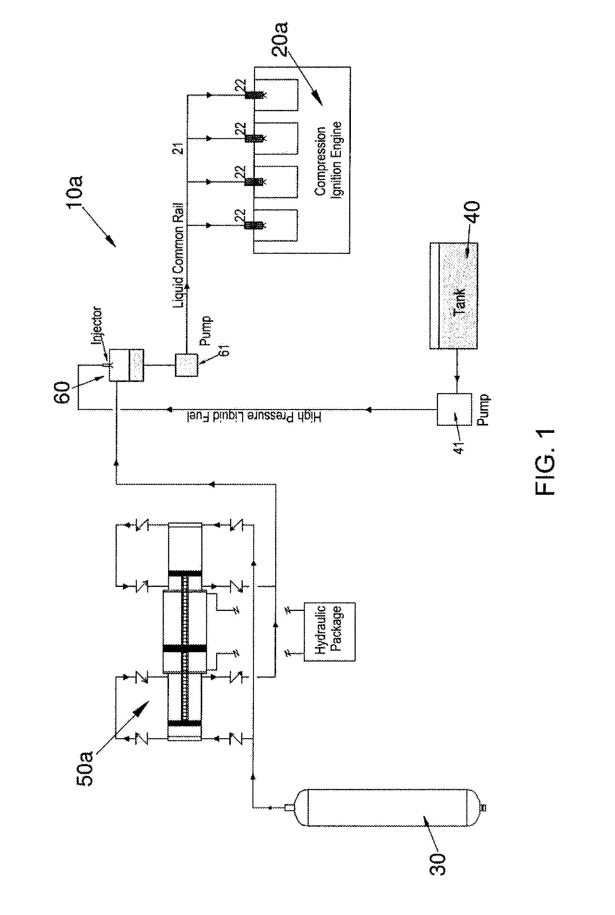
[0071]FIG. 1 shows a vehicle fuel system 10a. The vehicle fuel system 10a includes an engine in the form of a common rail direct injection engine 20a, a gas pressure vessel 30, a diesel storage vessel 40, an associated gas pressurisation system in the form of gas booster 50a and a mixing system including a first mixer 60.

[0072]In this disclosure the use of a reference numeral followed by a lower case letter indicates alternative embodiments of a general element identified by the reference numeral. Thus for example a gas booster 50a is similar to but not identical to a gas booster 50b. Further, references to an element identified only by the numeral refer to all embodiments of that element. Thus for example a reference to a gas booster 50 is intended to include both the gas booster 50a and the gas booster 50b.

[0073]The common rail engine 20a is fitted with a common rail system including a liquid fuel common rail 21. Connected to the liquid fuel common rail 21 is a set of liquid fuel...

second embodiment

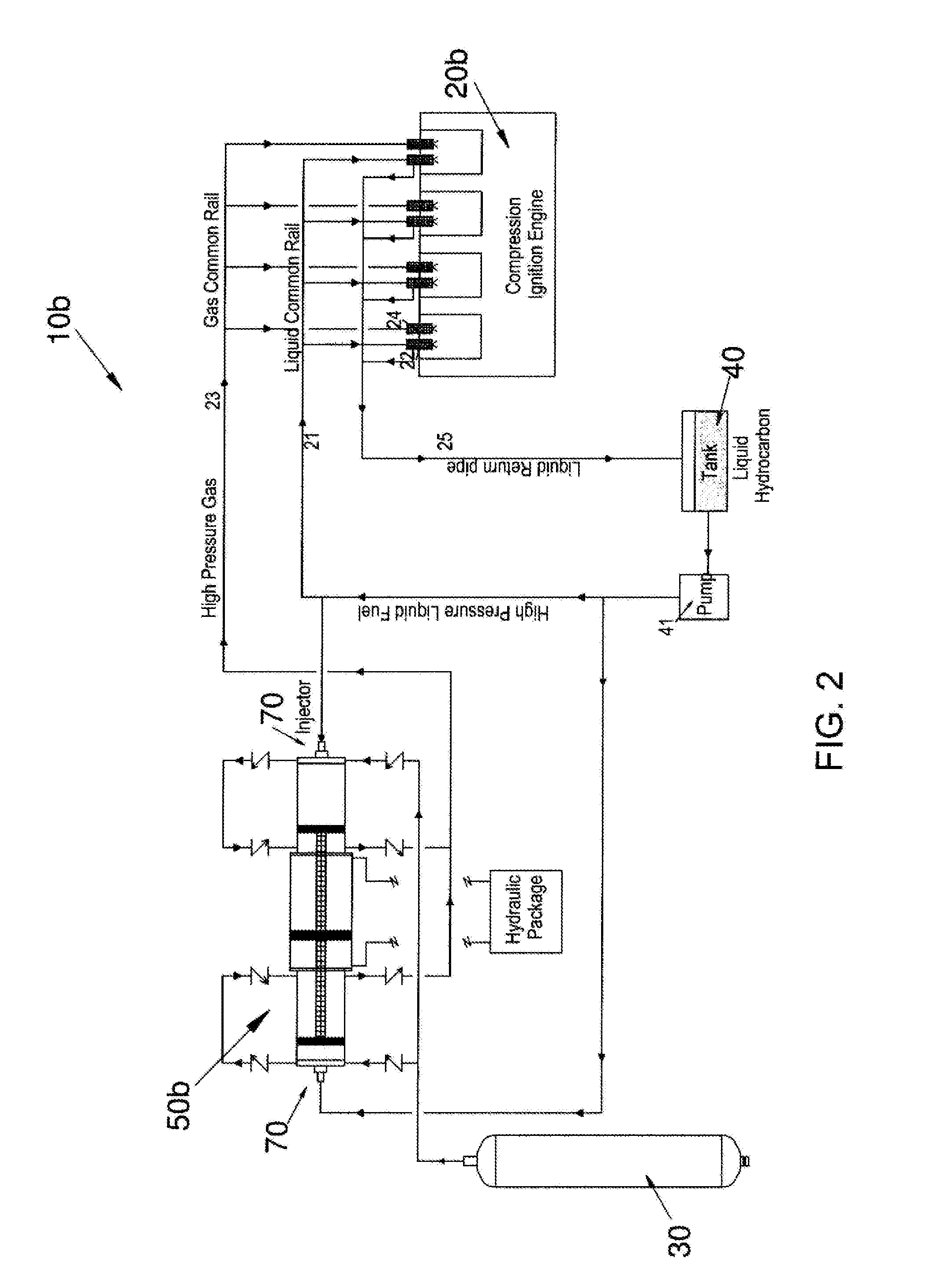
[0087]FIG. 2 shows a vehicle fuel system 10b and like numbering from FIG. 1 is used. The vehicle fuel system 10b includes an engine in the form of a common rail direct injection engine 20b, a gas pressure vessel 30, a diesel storage vessel 40, an associated gas pressurisation system in the form of a gas booster 50b and a second mixer in the form of mixing systems 70 comprising an injector and an intake cylinder on either end of the gas booster 50b.

[0088]The gas pressure vessel 30 holds natural gas. The gas booster 50b increases the pressure of the natural gas as it is withdrawn from the pressure vessel 30 to a desired pressure. The mixing systems 70 are integrated into the gas booster 50b.

[0089]The diesel storage vessel 40 is typically used to hold diesel. However, it should be appreciated that other liquid fuels may also be utilised. The diesel storage vessel 40 is therefore a liquid storage vessel. A diesel storage vessel pump 41 is connected to the diesel storage vessel 40 in o...

third embodiment

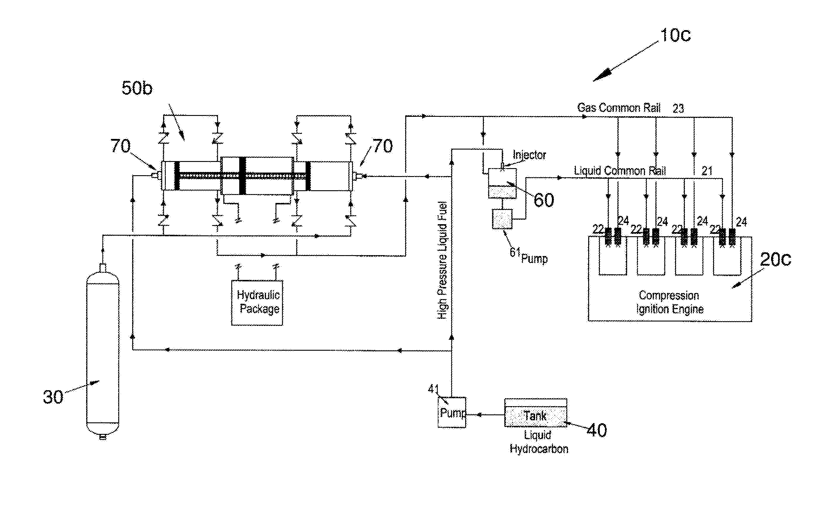
[0098]FIG. 3 shows the present invention including a vehicle fuel system 10c, comprising the combination of the first two embodiments (i.e., FIG. 2 and FIG. 3) of the vehicle fuel system 10a and system 10b described above. The vehicle fuel system 10c in FIG. 3 includes an engine in the form of a common rail direct injection engine 20b, a gas pressure vessel 30, a diesel storage vessel 40, an associated gas pressurisation system in the form of gas booster 50b and a mixing system including a first mixer 60 and mixing systems 70.

[0099]The gas pressure vessel 30 holds natural gas. The gas booster 50b increases the pressure of the natural gas as it is withdrawn from the gas pressure vessel 30 to a desired pressure. Similar to the above, the diesel storage vessel 40 is typically used to hold diesel. However, it should be appreciated that other liquid fuels may also be utilised. A diesel storage vessel pump 41 is connected to the diesel storage vessel 40 in order to pump diesel from the di...


PUM


Abstract

An improved vehicle fuel system enables mixing of natural gas and a liquid fuel upstream of a combustion cylinder. According to some embodiments the system includes: a gas pressure vessel and associated gas pressurisation system to deliver natural gas at a desired pressure; a liquid fuel storage vessel and associated reservoir pump to deliver liquid fuel at a desired pressure; a mixing system configured to receive and mix the liquid fuel from the liquid fuel storage vessel and natural gas from the gas pressure vessel to produce a homogeneous fluid fuel mixture; and a common rail system connecting the mixing system to an engine that consumes the homogeneous fluid fuel.

Description

FIELD OF THE INVENTION[0001]This invention relates to a vehicle fuel system. In particular, the invention relates to a vehicle fuel system, typically for direct injected compression ignition or spark ignition engines, utilising natural gas fuel in combination with liquid fuels including hydrocarbons, ethers, alcohols and acetyls.BACKGROUND TO THE INVENTION[0002]Vehicles that are powered by natural gas are typically considered to be more environmentally friendly than petrol or diesel fuelled vehicles. The carbon emissions of natural gas vehicles are considerably lower than that of vehicles powered using liquid fuels such as petrol or diesel. Traditionally there is also a cost saving in relation to the price of natural gas when compared to diesel fuels.[0003]Spark ignition (petrol) engines may be modified relatively simply to operate on natural gas or liquid petroleum gas. However these engines have limited suitability for use in mobile high horsepower applications such as highway tru...

Claims


Application Information

Patent Timeline
Patent Type & Authority Applications(United States)
IPC IPC(8): F02M37/00F02M61/14F02M55/02F02M21/02F02M37/14
CPCF02M37/0064F02M21/0215F02M21/0221F02M61/14F02M21/0248F02M37/14F02M55/025F02M21/0245F02D19/10F02B7/06F02D19/0663Y02T10/30
Inventor FEKETE, DEREK SHANEWHITEMAN, PAUL ANTHONY
Owner MOSAIC TECH DEV
Why Eureka
Try Eureka