Integrated Methane Refrigeration System for Liquefying Natural Gas

a refrigeration system and natural gas technology, applied in refrigeration, liquidation, lighting and heating apparatus, etc., can solve the problems of reduced performance, increased mechanical stress, and large heat exchangers, and achieve the effect of reducing the efficiency of the nitrogen recycle expander process and reducing the mechanical stress

Active Publication Date: 2016-10-27
AIR PROD & CHEM INC
View PDF4 Cites 36 Cited by
  • Summary
  • Abstract
  • Description
  • Claims
  • Application Information

AI Technical Summary

Benefits of technology

[0031](ii) receive and sub-cool, by indirect heat exchange with the second flash gas stream, a first supplementary LNG stream, prior to at least a portion of said stream being received by a pressure reduction device and phase separation vessel arranged and operable to expand and separate said at least a portion of the first supplementary LNG stream so to produce additional vapor and liquid for forming, respectively, the second flash gas stream and third LNG stream.

Problems solved by technology

Designing and operating such a LNG plant on a floating platform poses, however, a number of challenges that need to be overcome.
Conventional liquefaction processes that use mixed refrigerant (MR) involve two-phase flow at certain points of the refrigeration cycle, which may lead to reduced performance due to liquid-vapor maldistribution if employed on a floating platform.
In addition, in any of the refrigeration cycles that employ a liquefied refrigerant, liquid sloshing will cause additional mechanical stresses.
However, the nitrogen recycle expander process has a relatively lower efficiency and involves larger heat exchangers, compressors, expanders and pipe sizes.

Method used


Image

  • Integrated Methane Refrigeration System for Liquefying Natural Gas
  • Integrated Methane Refrigeration System for Liquefying Natural Gas
  • Integrated Methane Refrigeration System for Liquefying Natural Gas

Examples


example

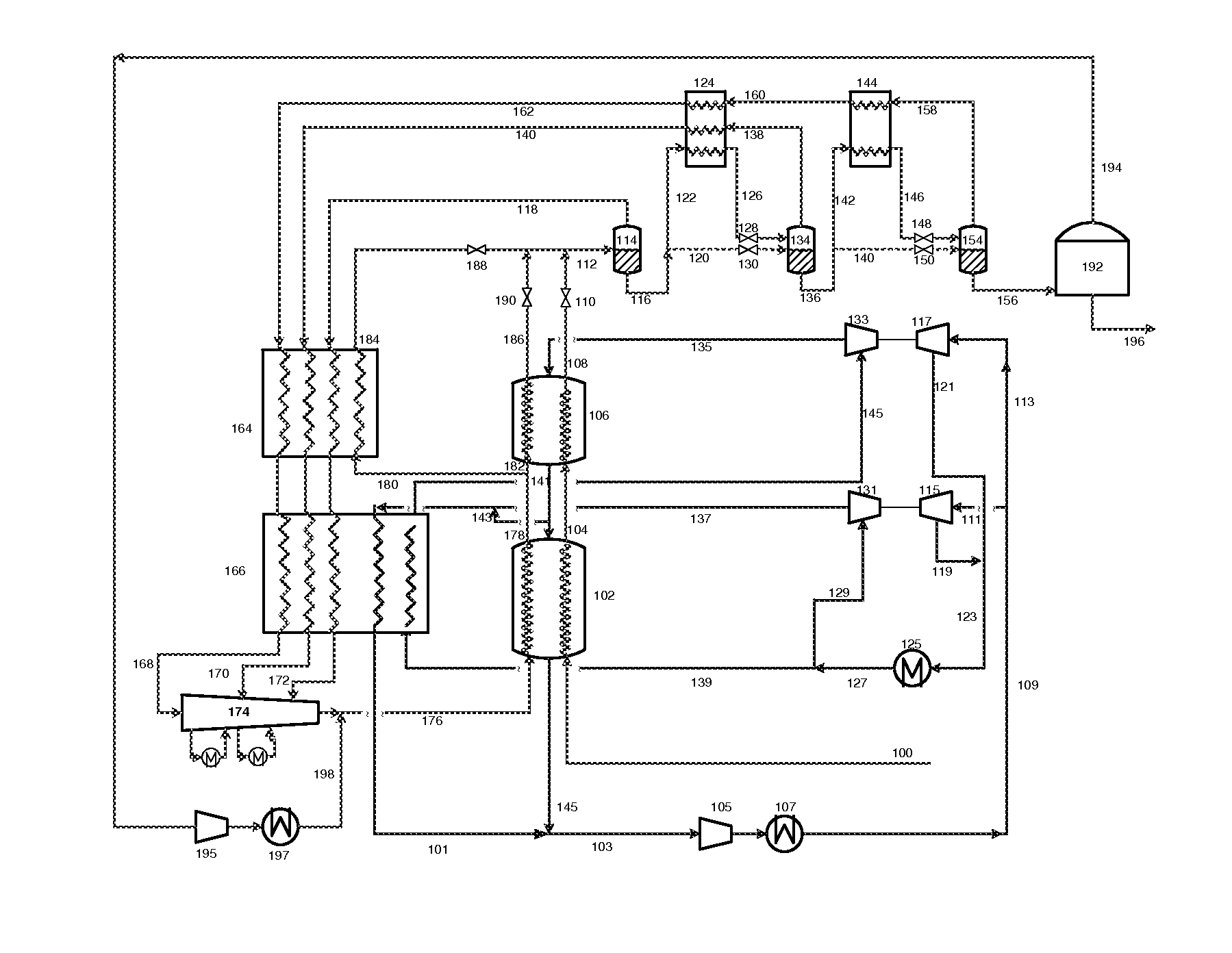
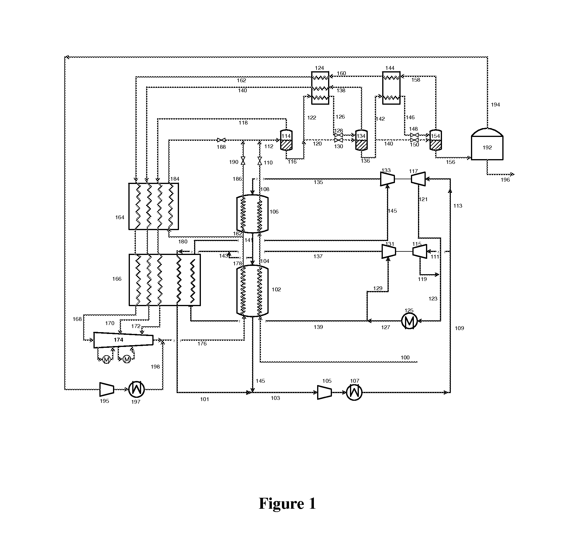
[0234]In order to illustrate the operation of the invention, the method of liquefying a natural gas feed stream described and depicted in FIG. 1 was simulated, using ASPEN Plus software. The simulation was conducted on the basis of a natural gas feed stream that comprised 100% methane and a gaseous refrigerant that comprised 100% methane also.

[0235]Table 1 below lists the conditions and compositions of various streams during the simulation (the reference numerals used in Table 1 being the same as those used in FIG. 1). In this simulation, the total specific power of the process is minimized by controlling parameters such as the pressure of each stage of flash, the outlet temperature of each heat exchanger, the split ratio of each stream that is split or divided, and the outlet pressure of each expander, as is known in the art.

[0236]Table 2 shows a comparison between method of FIG. 1, simulated as described above, and the state of the art three-compander nitrogen recycle process, whe...


PUM


Abstract

Described herein is a method and system for liquefying a natural gas feed stream to produce an LNG product. The natural gas feed stream is liquefied, by indirect heat exchange with a gaseous methane or natural gas refrigerant circulating in a gaseous expander cycle, to produce a first LNG stream. The first LNG stream is expanded, and the resulting vapor and liquid phases are separated to produce a first flash gas stream and a second LNG stream. The second LNG stream is then expanded, with the resulting vapor and liquid phases being separated to produce the second flash gas stream and a third LNG stream, all or a portion of which forms the LNG product. Refrigeration is recovered from the second flash gas by using said stream to sub-cool the second LNG stream or a supplementary LNG stream.

Description

BACKGROUND[0001]The present invention relates to a method and system for liquefying a natural gas feed stream to produce a liquefied natural gas (LNG) product.[0002]The liquefaction of natural gas is a highly important industrial process. The worldwide production capacity for LNG is more than 300 MTPA, and a variety of refrigeration cycles for liquefying natural gas have been successfully developed, and are known and widely used in the art.[0003]Some cycles utilize a vaporized or vaporizing refrigerant to provide the cooling duty for liquefying the natural gas. In these cycles, the initially gaseous, warm refrigerant (which may, for example, be a pure, single component refrigerant, or a mixed refrigerant) is compressed, cooled and liquefied to provide a liquid refrigerant. This liquid refrigerant is then expanded so as to produce a cold vaporized or vaporizing refrigerant that is used to liquefy the natural gas via indirect heat exchange between the refrigerant and natural gas. The ...

Claims


Application Information

Patent Timeline
Patent Type & Authority Applications(United States)
IPC IPC(8): F25J1/00F25J1/02
CPCF25J1/0082F25J1/0223F25J1/0022F25J1/0042F25J2210/60F25J1/0037F25J1/004F25J1/005F25J1/0085F25J1/0092F25J1/0202F25J1/0208F25J1/021F25J1/0263F25J1/0267F25J1/0288F25J1/0292F25J2220/62F25J2230/08F25J2245/90F25J2270/06F25J2270/16F25J1/0278F25J1/008F25J3/04787F25J2215/60
Inventor ROBERTS, MARK JULIANLIU, YANGCHEN, FEI
Owner AIR PROD & CHEM INC
Why Eureka
Try Eureka