
Imaging module and imaging device

Active Publication Date: 2016-10-27
RICOH KK
View PDF1 Cites 3 Cited by
  • Summary
  • Abstract
  • Description
  • Claims
  • Application Information

AI Technical Summary

Benefits of technology

The present invention is about an imaging device that brings together an image sensor and a spatial modulation element in a way that reduces the distance between them and allows for precise placement of the sensor and the modulation element. This results in a high-quality image capture.

Problems solved by technology

And additionally, a problem on mounting has occurred in that the size of an imaging device increases, a conflict of mounting position between optical components such as a movable mirror, and the like occurs, high accuracy is required for an arrangement position between the coded-aperture pattern and the image sensor, it is difficult to deal with the change of an optical system such as a lens, or the like, and so on.

Method used


Image

  • Imaging module and imaging device
  • Imaging module and imaging device
  • Imaging module and imaging device

Examples


Embodiment Construction

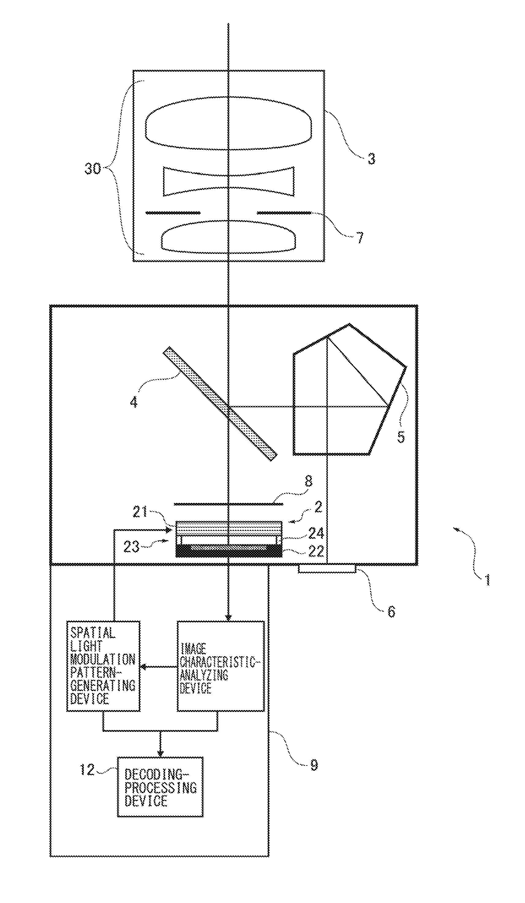
[0019]An imaging device shown in FIG. 1 in the present embodiment has an imaging module 2 which obtains an image, an image-forming optical system 3 which images and emits an incident luminous flux toward the imaging module 2, and a mirror 4 which selects an optical path from the image-forming optical system 3.

[0020]The imaging device 1 also has a finder 6 which confirms a visual field, a deflection element 5 which deflects light from the mirror 4 to the finder 6, a shutter 8 which determines an exposure time, and a controller 9 which controls those members.

[0021]The above structure other than the imaging module 2 is equal to a general single-lens reflex camera; however, the structure can be a structure of a so-called mirrorless single-lens reflex camera in which the finder 6 and the mirror 4 are removed, and instead a liquid crystal monitor is included.

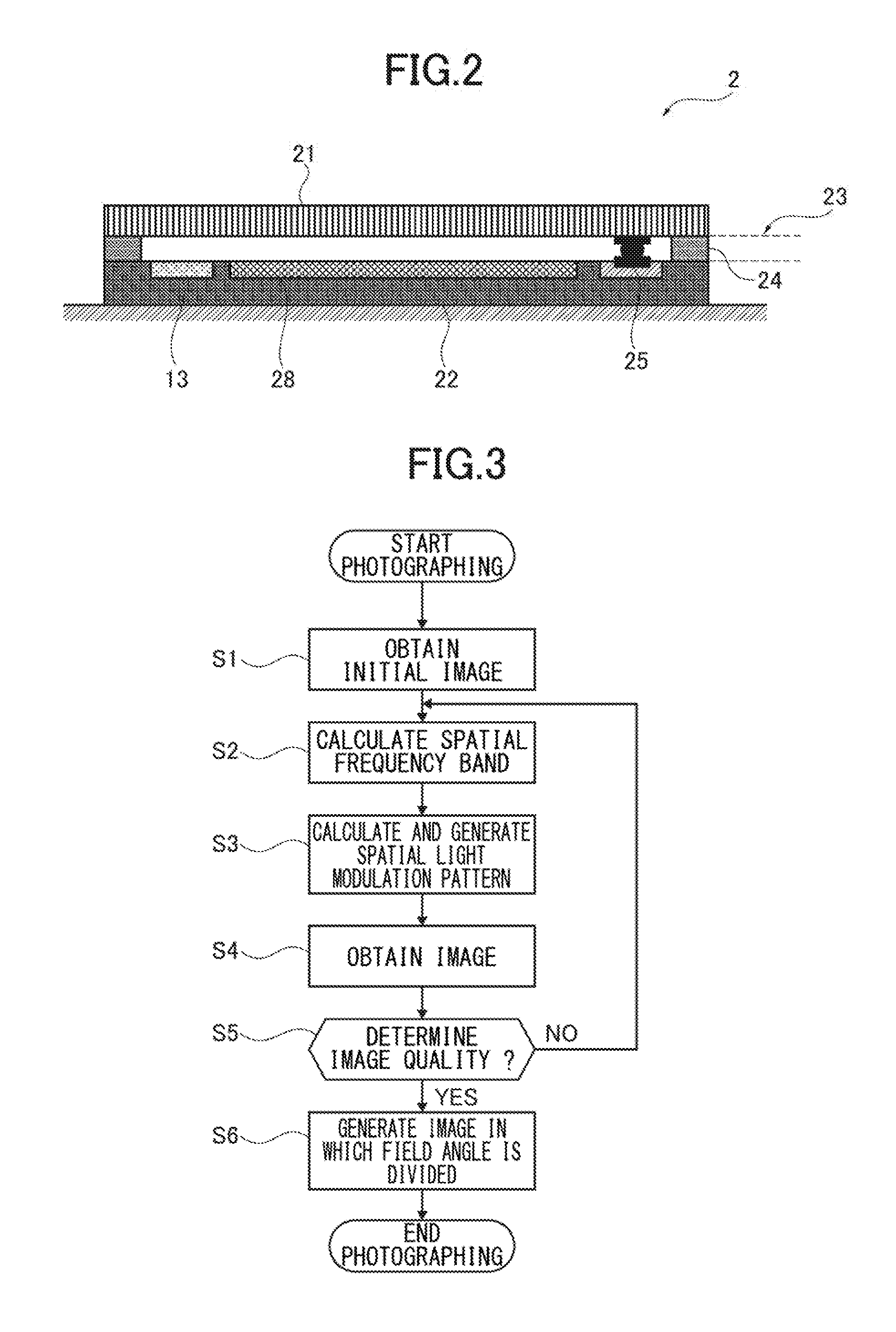
[0022]With reference to FIG. 2, a structure of the imaging module 2 will be explained.

[0023]The imaging module 2 has a spatial light...


PUM


Abstract

An imaging module has a spatial light modulation element which applies spatial modulation to an incident luminous flux and emits it; an image sensor which obtains the luminous flux to which the spatial modulation has been applied by the spatial light modulation element as image information; and a fixing part which integrally fixes the spatial light modulation element and the image sensor, and the fixing part has a gap-defining member which is arranged between the spatial light modulation element and the image sensor and forms a gap structure having a certain distance, and an imaging device includes the imaging module.

Description

TECHNICAL FIELD[0001]The present invention relates to an imaging module and an imaging device using coded-aperture imaging.BACKGROUND ART[0002]An imaging device represented by a camera is widely used for photographing for appreciating photography, an industrial measurement / object recognition system, risk detection for vehicle, a crime-prevention monitoring system, and the like. In those use forms, it is often necessary to obtain not only an image of a photographic subject but also spatial information such as a distance, a visual field direction, and the like.[0003]As a technique which makes it possible to obtain the spatial information, by use of an image sensor and a coded-aperture pattern, a technique is known in which information on a space and an incidence angle of a luminous flux incident to the image sensor is obtained by performing decoding processing based on Fourier transform (for example, see Japanese Patent Application Publication No. 2008-191661).[0004]Additionally, by u...

Claims


Application Information

Patent Timeline
IPC IPC(8): H04N5/232G02F2/00G02B26/02G02F1/133H04N5/225G02B26/00
CPCH04N5/23235H04N5/2252H04N5/2253H04N5/2254G02F2/00G02B26/004G02B26/02G02F1/13306H04N5/2257G03B11/00G02B2207/129H04N23/57H04N23/55H04N23/75H04N25/00H04N23/815H04N23/51H04N23/54
Inventor SANGU, SUGURU
Owner RICOH KK
Features
  • Generate Ideas
  • Intellectual Property
  • Life Sciences
  • Materials
  • Tech Scout
  • Unparalleled Data Quality
  • Higher Quality Content
  • 60% Fewer Hallucinations
Learn More