Procedures for vascular occlusion

a technology of vascular occlusion and implantable devices, which is applied in the field of implantable devices, can solve the problems of weakened vessel walls, affecting associated body functions, and presenting complications or affecting the function of associated bodies, and achieves the effect of easy conformation

Active Publication Date: 2016-11-03
TYCO HEALTHCARE GRP LP
View PDF0 Cites 23 Cited by
  • Summary
  • Abstract
  • Description
  • Claims
  • Application Information

AI Technical Summary

Benefits of technology

[0004]At least one aspect of the disclosure provides methods for implanting an occluding device or devices (e.g., stent or stents) in the body. The occluding device can easily conform to the shape of the tortuous vessels of the vasculature. The occluding device can direct the blood flow within a vessel away from an aneurysm. Additionally, such an occluding device can allow adequate blood flow to be provided to adjacent structures such that those structures, whether they are branch vessels or oxygen demanding tissues, are not deprived of the necessary blood flow.

Problems solved by technology

Lumens in the body can change in size, shape, and / or patency, and such changes can present complications or affect associated body functions.
This is a result of the vessel wall being weakened by disease, injury or a congenital abnormality.
Aneurysms have thin, weak walls and have a tendency to rupture and are often caused or made worse by high blood pressure.
The mere presence of an aneurysm is not always life-threatening, but they can have serious heath consequences such as a stroke if one should rupture in the brain.
Additionally, a ruptured aneurysm can also result in death.

Method used


Image

  • Procedures for vascular occlusion
  • Procedures for vascular occlusion
  • Procedures for vascular occlusion

Examples


Embodiment Construction

[0103]In the following detailed description, numerous specific details are set forth to provide a full understanding of the subject technology. It will be apparent, however, to one ordinarily skilled in the art that the subject technology may be practiced without some of these specific details. In other instances, well-known structures and techniques have not been shown in detail so as not to obscure the subject technology.

Occluding Device

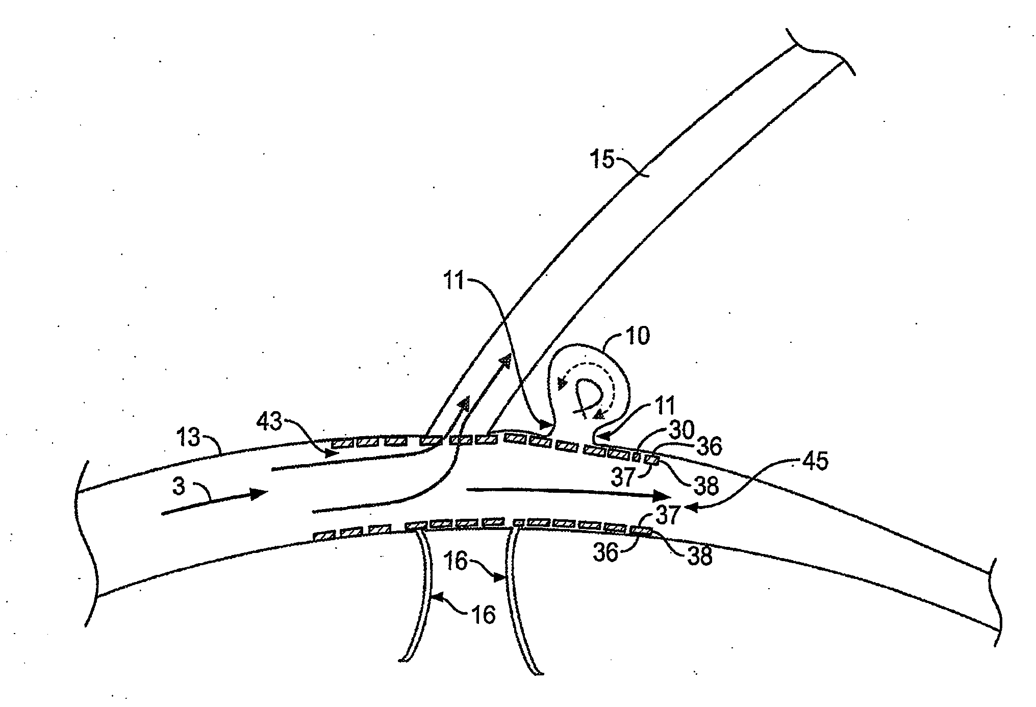
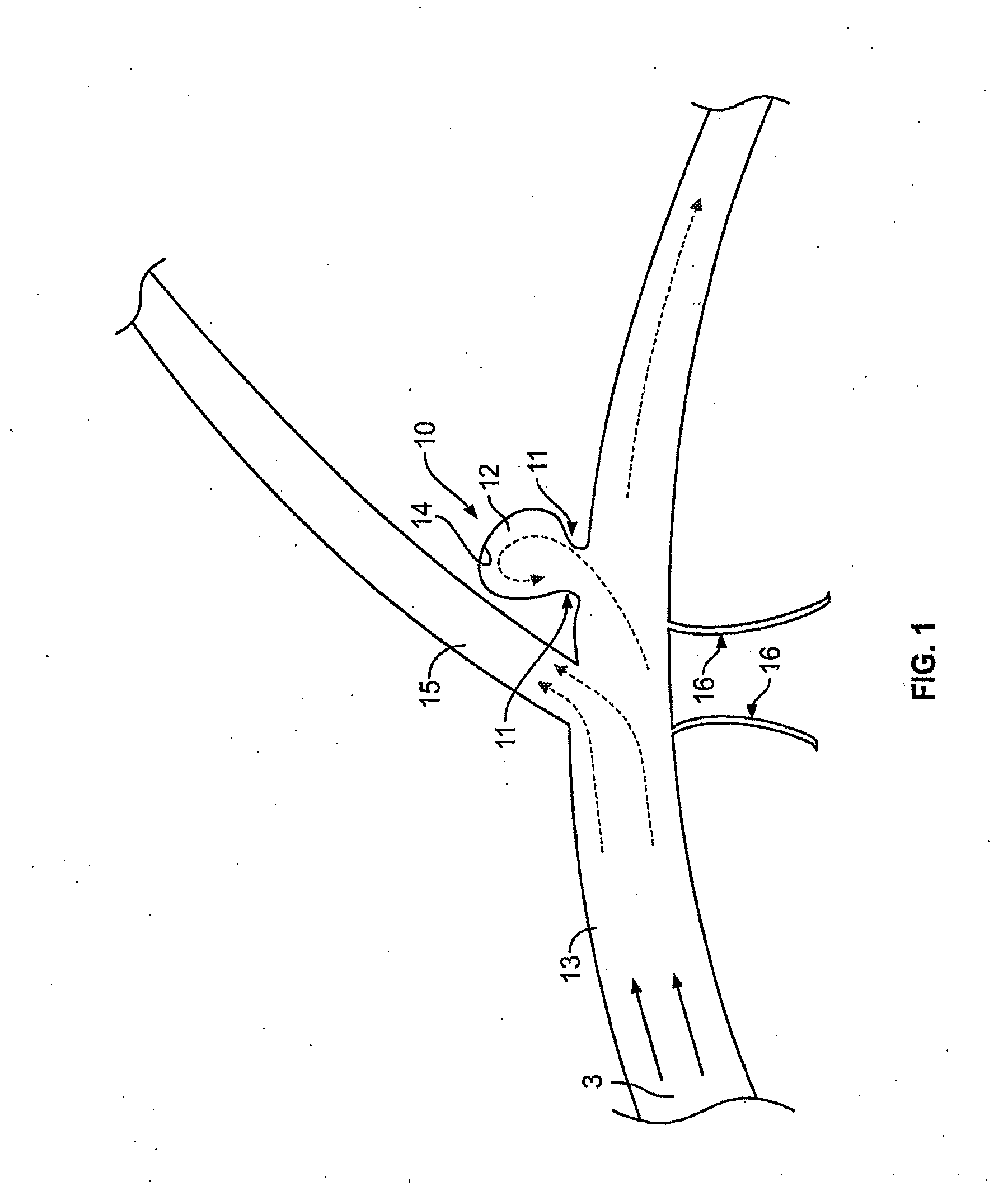
[0104]FIG. 1 illustrates a typical cerebral aneurysm 10. A neck 11 of the aneurysm 10 can typically define an opening of between about 2 to 25 mm, though other sizes and ranges are also possible. As is understood, the neck 11 connects the vessel 13 to the lumen 12 of the aneurysm 10. As can be seen in FIG. 1, the blood flow 3 within the vessel 13 is channeled through the lumen 12 and into the aneurysm. In response to the constant blood flow into the aneurysm, the wall 14 of lumen 12 continues to distend and presents a significant risk of rupturing....


PUM


Abstract

A method of reducing blood flow within an aneurysm includes: injecting a contrast agent into a blood vessel including an aneurysm; expanding a stent, from a delivery device, across the aneurysm; and confirming that a stagnated area forms in the aneurysm. The stagnated area can form a crescent shape, a mushroom shape, a hemispherical shape, and/or a flat side. Upon confirming that the stagnated area forms in the aneurysm, the delivery device can be withdrawn from the blood vessel. The stagnated area can include the contrast agent. If the stagnated area does not form in the aneurysm, a second occluding device may be deployed. After withdrawing the delivery device, substantially all of the aneurysm progressively thromboses

Description

[0001]This application is a continuation of U.S. application Ser. No. 14 / 791,617, filed Jul. 6, 2015, which is a continuation of U.S. application Ser. No. 13 / 652,591, filed Oct. 16, 2012, now issued U.S. Pat. No. 9,095,460 on Aug. 4, 2015, which is a continuation of U.S. application Ser. No. 12 / 751,997, filed Mar. 31, 2010, now issued as U.S. Pat. No. 8,409,269 on Apr. 2, 2013, which claims benefit under 35 U.S.C. §119(e) to U.S. Provisional Patent Application No. 61 / 288,525, filed Dec. 21, 2009, each of the above applications being expressly incorporated herein by reference in its entirety.BACKGROUND[0002]The present application generally relates to implantable devices for use within a patient's body and, more particularly, relates to methods for implanting occluding devices in a patient's body and monitoring an occlusion.[0003]Lumens in the body can change in size, shape, and / or patency, and such changes can present complications or affect associated body functions. For example, t...

Claims


Application Information

Patent Timeline
Patent Type & Authority Applications(United States)
IPC IPC(8): A61F2/82A61M5/00A61F2/95A61B17/12A61F2/90
CPCA61F2/82A61B17/12118A61M5/007A61B2017/1205A61F2/95A61F2002/823A61B17/12172A61F2/90A61F2002/826A61F2250/0018A61F2250/0026A61F2250/0065A61F2230/0078A61F2230/0091A61F2230/0095A61F2/013A61B17/12036A61B17/12109A61B17/12177A61F2/966A61B2017/00336A61B2017/12054A61B2090/3966A61B17/320758A61B2017/22079A61B2017/320716A61B2017/320766A61B2017/320791A61F2/852A61F2002/9528A61F2/011A61F2/01A61M25/00A61F2/06A61M29/00
Inventor BEREZ, AARON LEETRAN, QUANG QUOC
Owner TYCO HEALTHCARE GRP LP
Why Eureka
Try Eureka