
METAL-BONDED RE-Fe-B MAGNETS

Inactive Publication Date: 2016-11-03
INSTITUT JOZEF STEFAN
View PDF2 Cites 7 Cited by
  • Summary
  • Abstract
  • Description
  • Claims
  • Application Information

AI Technical Summary

Benefits of technology

The present invention provides bonded magnets that can overcome the limitations of conventional bonded magnets and can be used at temperatures above 200°C. The magnets use LMP metals or LMP alloys as the binder, which have higher temperature limits. The magnets exhibit high remanent magnetization and energy product. The use of LMP metals or alloys as the binder raises the polymer binder's temperature limit. The bonded magnets are made using a new technique called Spark-Plasma Sintering / Pulsed Electric Current Sintering, which allows for quick and accurate temperature control and preserves the initial microstructure of the magnetic material. This technique also reduces the processing time and prevents unwanted grain-growth.

Problems solved by technology

Due to poor thermal stability of polymer-bonded magnets, the temperature limit for applications using such magnets is set at max.
Usually, such rapid quenching results in amorphous microstructure.
Later the ribbons are crushed and subjected to appropriate heat treatment, which results in nucleation and growth of nano-grains.
The drawback of this method is lower quench rate, which can lead to an undesired microstructure, but with some adjustments, these obstacles can be solved.
However, due to polymer binder these magnets are only suitable for temperatures up to 180° C., which cuts-down many potential applications, demanding higher thermal stability.

Method used


Image

  • METAL-BONDED RE-Fe-B MAGNETS
  • METAL-BONDED RE-Fe-B MAGNETS
  • METAL-BONDED RE-Fe-B MAGNETS

Examples


Embodiment Construction

[0024]Object of the present invention is fabrication of metal-bonded magnets utilizing magnetically isotropic or anisotropic RE-Fe—B powder and LMP alloy as binding phase. More preferably, it consists of Nd—Fe—B powder blended with Zn powder as in the following example, with melting point of 420° C. Sintering temperature for these compacts is set at 400° C., pressure of 50-500 MPa is applied to assist the densification process. Consolidation time is kept to a minimum, around 5 minutes per cycle to preserve magnetic performance.

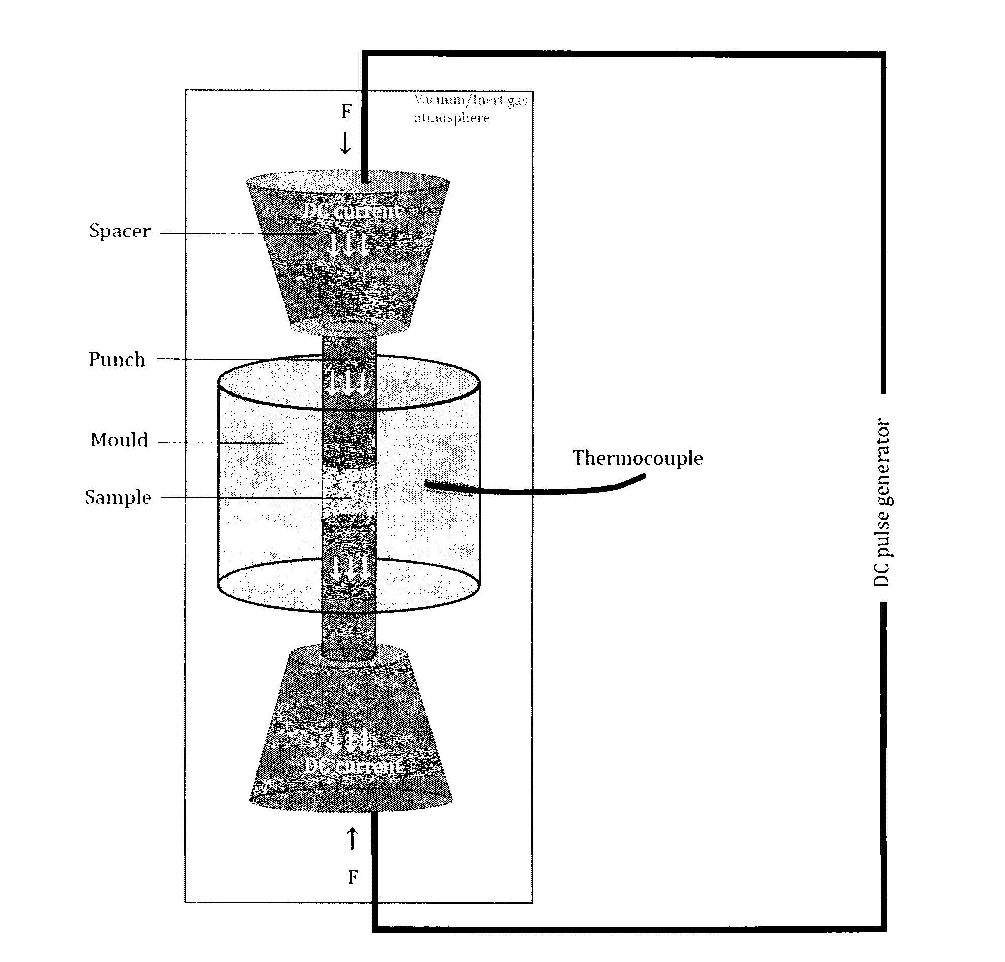
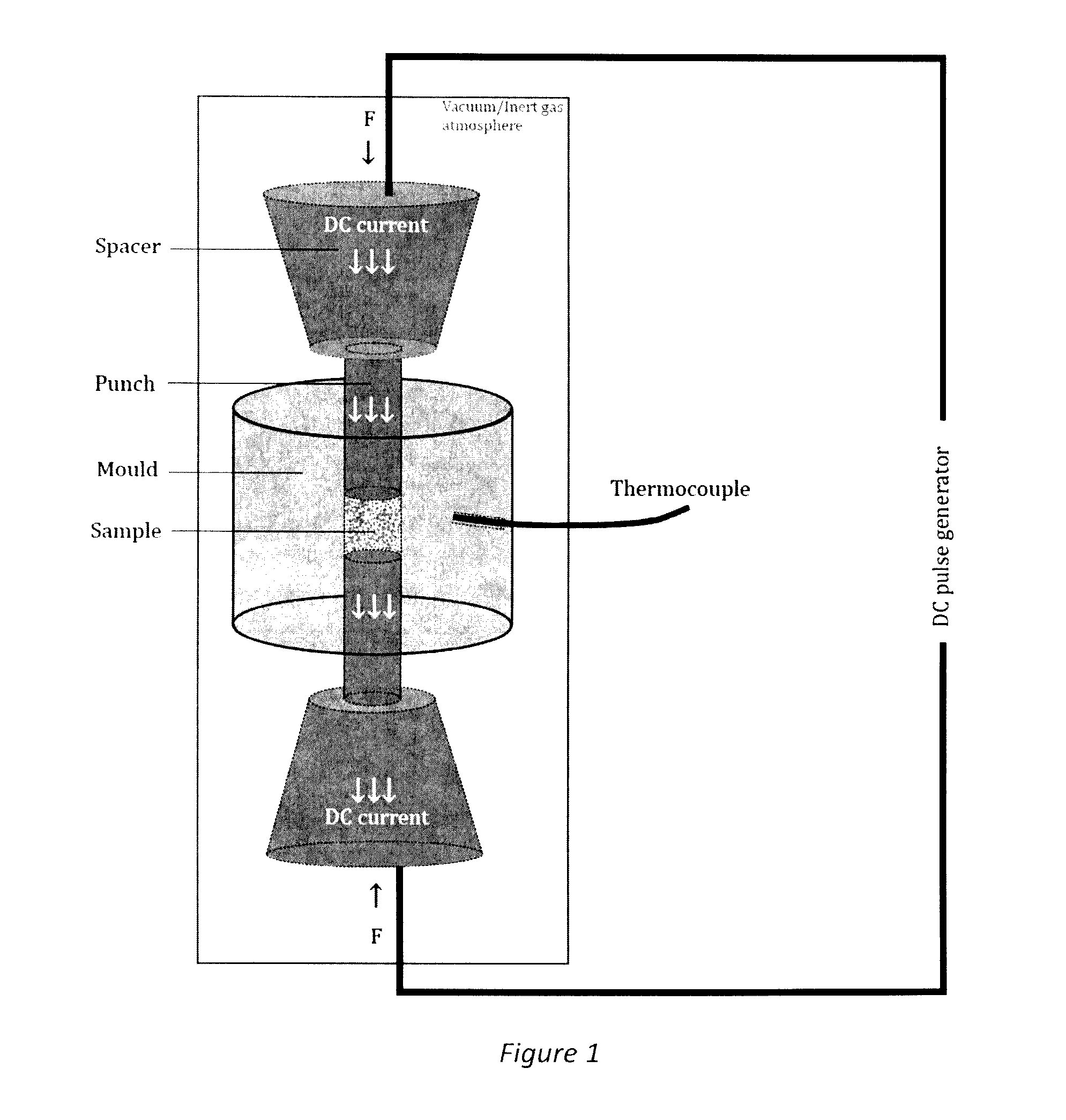
[0025]The example features a magnetic powder, made of crushed ribbons in the size range 60-325 μm and LMP particles added in the form of spheres in the size range 1 to 5 μm. The processing route includes mixing of the powders in different amounts and subjecting them to a hot-compaction cycle using a SPS machine. FIG. 1 shows a schematic of such a SPS machine, in which DC-pulses are applied to the powder mixture (sample) arranged in the mould. At the same time ...


PUM

PropertyMeasurementUnit
Temperatureaaaaaaaaaa
Fractionaaaaaaaaaa

Abstract

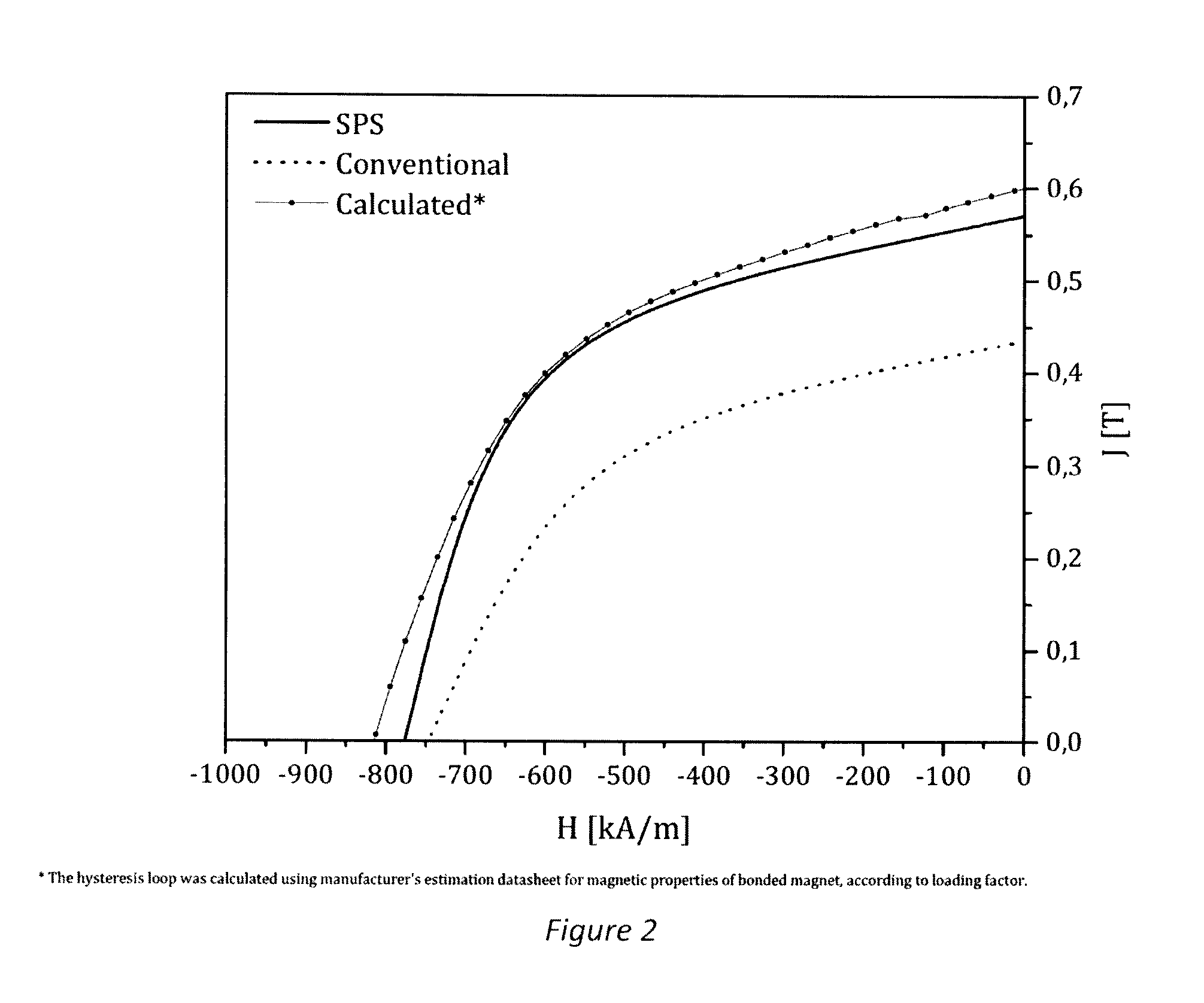
This invention relates to bonded magnets and the method for their production. Such magnets benefit from the fact that for binding, they utilize Low-Melting-Point metal or an alloy, and thus can be used at temperatures where conventional bonded magnets cannot operate. This composite magnet is made of magnetic phase and non-magnetic metallic binder. The mechanical and magnetic properties of metal-bonded magnets vary with the ratio of the two phases. The optimum result is achieved when adding 20-40 wt. % of binder. A huge difference can be observed between conventional and spark-plasma sintering (SPS) processing. An increase in remanence is up to 30%, as a consequence of simultaneous application of pressure and temperature. Additionally, minimized exposure time contributes to preservation of magnetic properties, which is a strong advantage of SPS technique. The value added of such magnets is the ability to withstand temperatures above 200° C., due to metallic matrix.

Description

FIELD OF THE INVENTION[0001]This invention relates to a novel concept of bonded magnets, more specifically metal-bonded magnets. These composites feature magnetic powder bonded with a low-melting-point (LMP) metal-matrix.BACKGROUND OF THE INVENTION[0002]Conventional bonded magnets are usually made of magnetic material and polymer binder and they are popular components for mild conditions where a complex-shape magnet is required. Such a polymer-bonded magnet is described, for example, in EP 2381452 A1. The magnet comprises magnet powder containing a rare-earth element and a resin part binding the magnet powder. Due to poor thermal stability of polymer-bonded magnets, the temperature limit for applications using such magnets is set at max. 180° C., although in most cases it is even lower.[0003]However, with a shift towards the use of these magnets in automotive applications where temperatures easily exceed 100° C., and in many cases higher, and with the additional problem of a corrosi...

Claims


Application Information

Patent Timeline
IPC IPC(8): H01F1/057H01F41/02B22F3/14
CPCH01F1/0577H01F41/0266B22F3/14H01F1/0578B22F3/105B22F2003/1051C22C9/04C22C12/00C22C13/00C22C19/03C22C21/10C22C21/12C22C21/14C22C23/04C22C38/002C22C38/005B22F1/09
Inventor KELHAR, LUKAMCGUINNES, PAULKOBE, SPOMENKA
Owner INSTITUT JOZEF STEFAN
Learn More