

Aerating system for hydraulic turbine
- Summary
- Abstract
- Description
- Claims
- Application Information
AI Technical Summary
Benefits of technology
Problems solved by technology
Method used
Image

Examples
Embodiment Construction
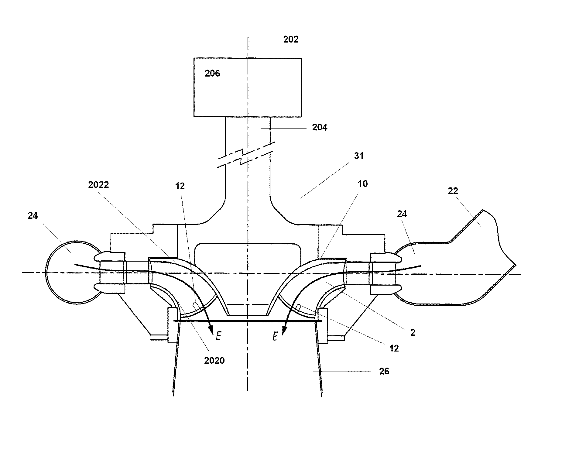
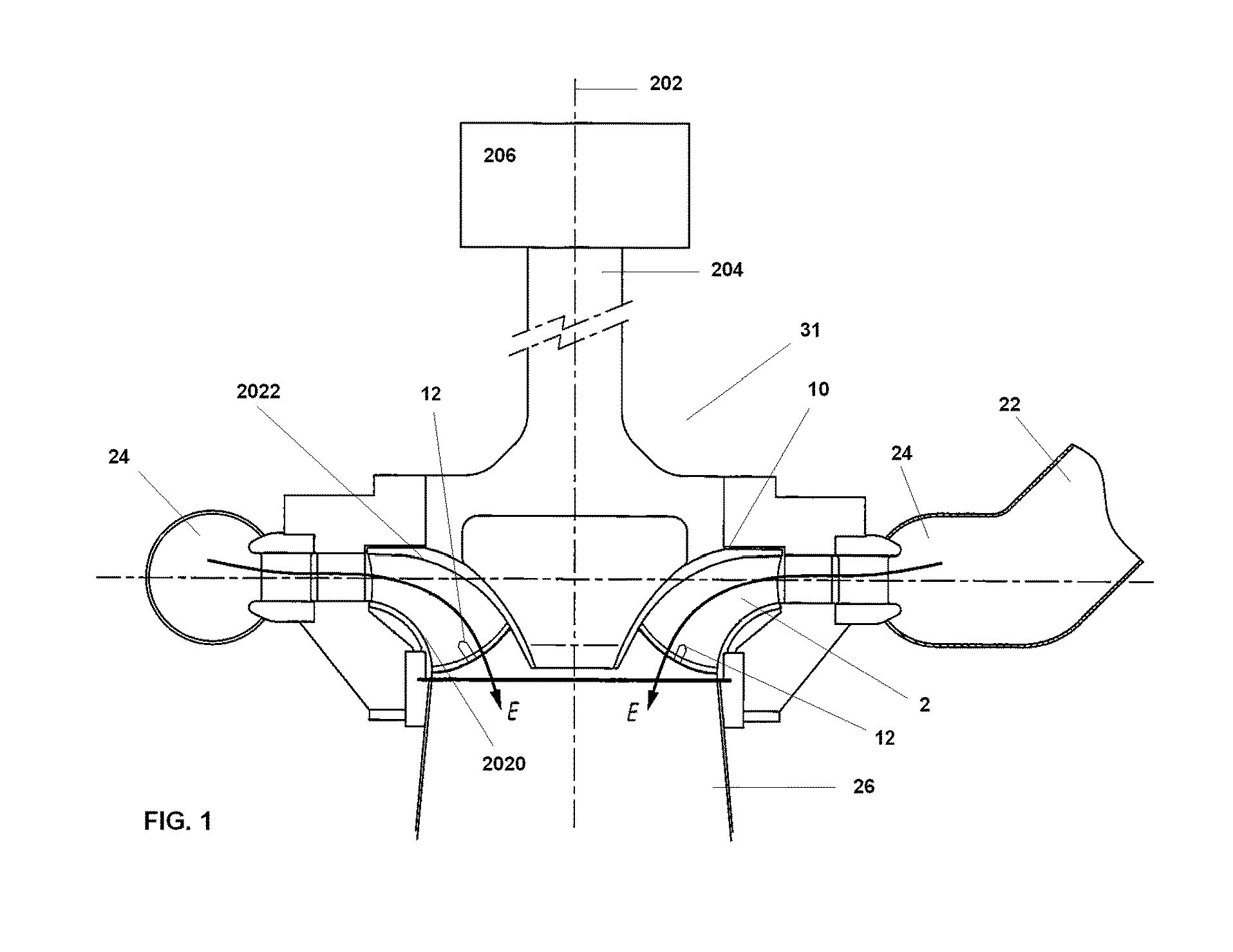
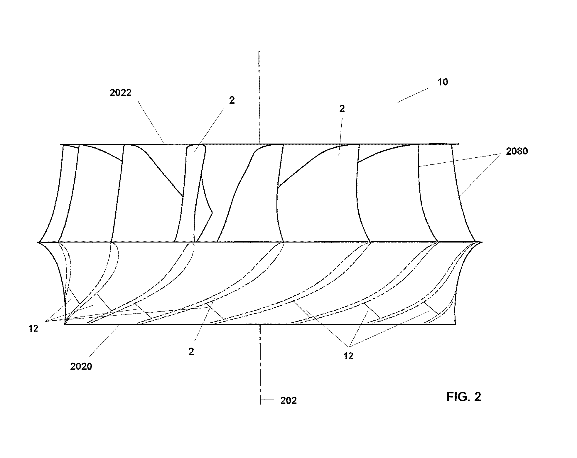
[0015]FIG. 1 shows an installation for the conversion of energy according to the present invention. This installation comprises a hydraulic turbine 31 that, in FIG. 1, is a Francis turbine. The rotating part of the hydraulic turbine 31 is a runner 10, in this FIG. 1, of the Francis type. This runner 10 rotates around a vertical axis 202, driving the rotation of a drive shaft 204. The drive shaft 204 is linked to a generator 206 for producing electricity. However, it is also possible to use the mechanical energy produced for driving another device. The water is stored up-stream in a water reservoir not shown in FIG. 1. Water is then then provided into the hydraulic turbine 31 via a pressure pipe 22 having a drop height defined by the difference in elevation between the water reservoir and the hydraulic turbine 31. The pressure pipe 22 ends into a cover 24 which surrounds the runner 10 and allows distributing water substantially uniformly around the vertical axis 202 within the runner...
PUM
 Abstract
Description
Claims
Application Information