Single-Phase Outer-Rotor Motor and Stator Thereof

a single-phase outer-rotor motor and stator technology, applied in the direction of rotating magnets, synchronous machines with stationary armatures, magnetic circuit rotating parts, etc., can solve the problems of limited stator size, noise, affecting the stability of the rotor during rotation, etc., to facilitate winding, reduce cogging torque, and operate smoothly

Inactive Publication Date: 2016-11-10
JOHNSON ELECTRIC SA
View PDF7 Cites 2 Cited by
  • Summary
  • Abstract
  • Description
  • Claims
  • Application Information

AI Technical Summary

Benefits of technology

[0021]In comparison with the conventional outer-rotor motor, the tooth tip of the stator of the motor of the present invention is tilted outwardly prior to the forming of the stator core, which enlarges the spacing between the tooth tips thus facilitating the winding. After the winding is completed, the tooth tip deforms to bend inwardly, such that the adjacent tooth tips form therebetween a narrow slot opening which can effectively reduce the cogging torque. Therefore, the motor can operate smoothly with low noise.

Problems solved by technology

For the single-phase outer-rotor motor, because the stator is disposed inside the rotor, the size of the stator is limited.
For facilitating the winding, teeth of the stator define therebetween slot openings with large width, such that the motor has a large cogging torque, which affects the rotor stability during rotation and produces noises.

Method used


Image

  • Single-Phase Outer-Rotor Motor and Stator Thereof
  • Single-Phase Outer-Rotor Motor and Stator Thereof
  • Single-Phase Outer-Rotor Motor and Stator Thereof

Examples


first embodiment

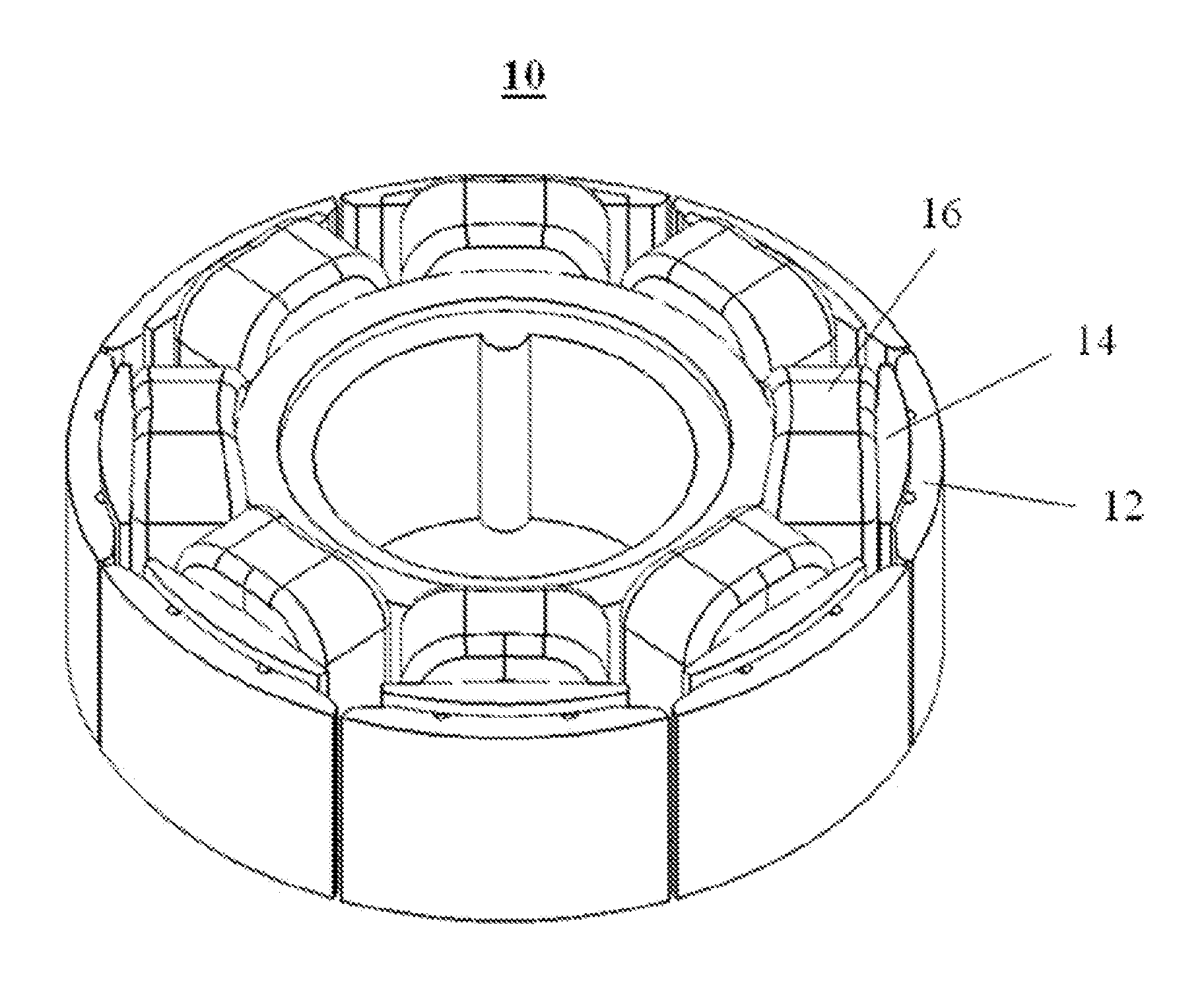
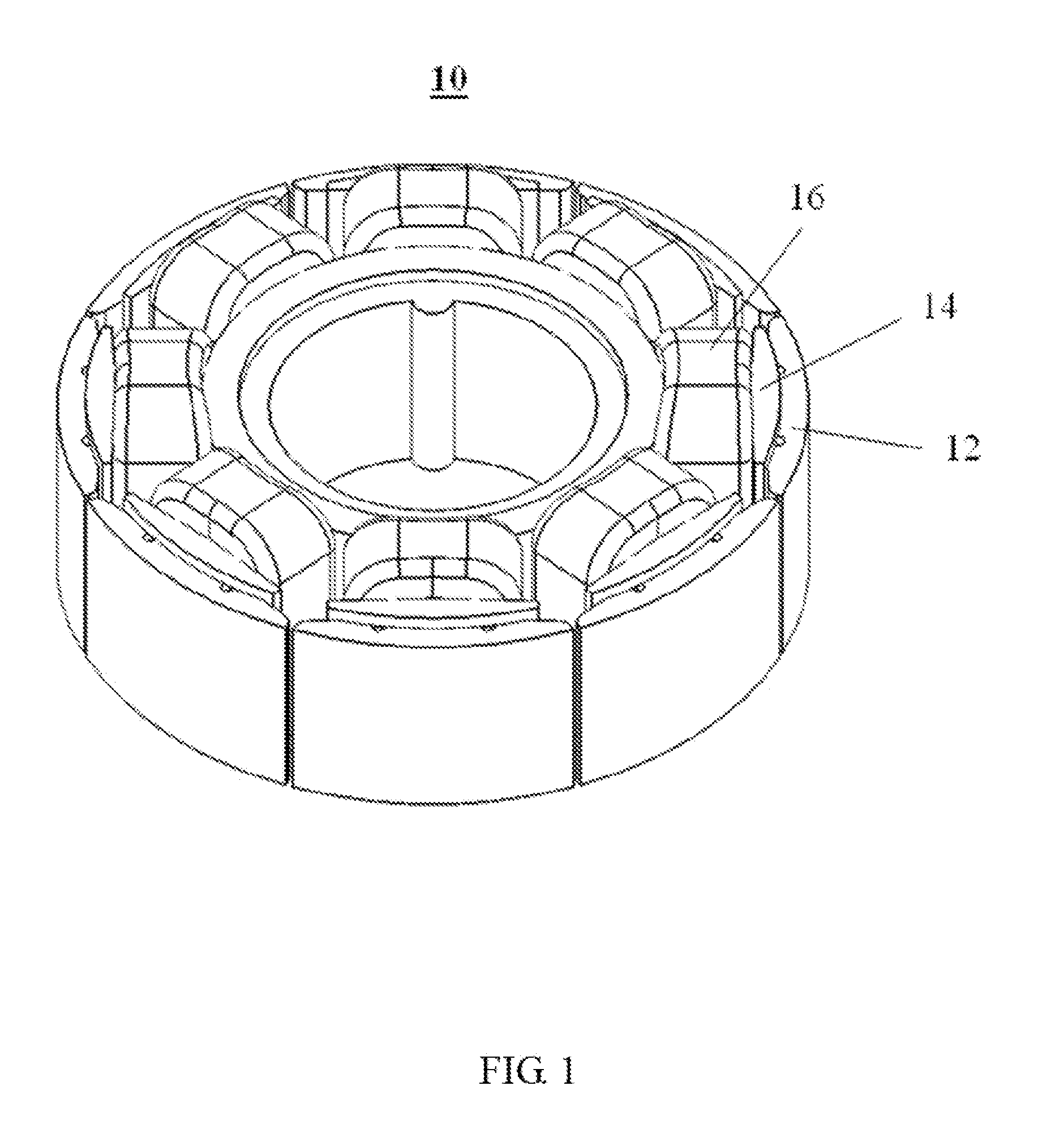
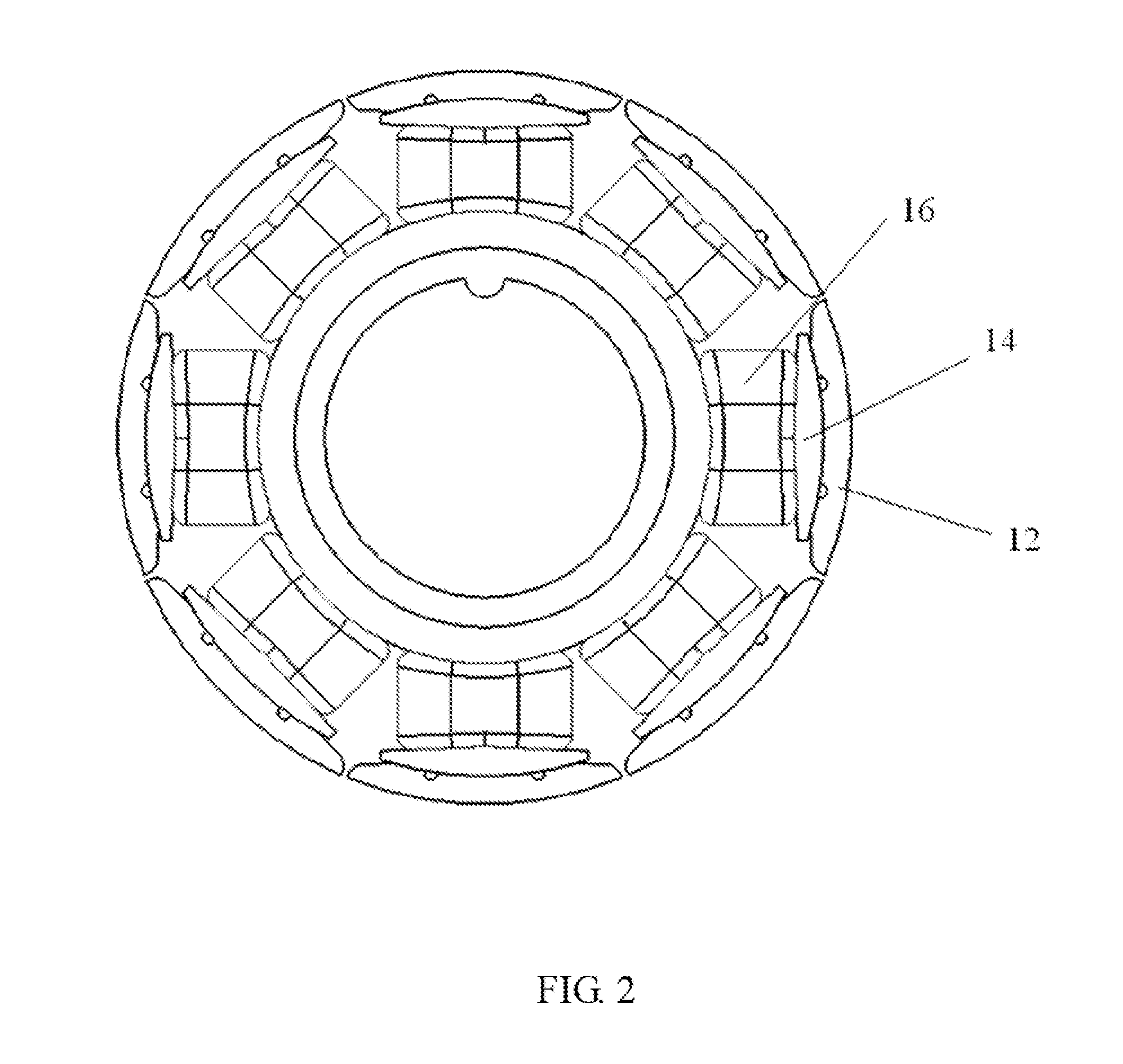
[0056]FIG. 1 through FIG. 4 illustrate a stator 10 according to a In this embodiment, the stator 10 includes a stator core 12, an insulating bracket 14 wrapping around the stator core 12, and windings 16 wound around the insulating bracket 14.

[0057]The stator core 12 is made by stacking magnetic-conductive materials such as silicon steel sheets. The stator core 12 includes an annular yoke 18, and a plurality of teeth 20 extending integrally and radially outwardly from an outer edge of the yoke 18. The teeth 20 are evenly disposed along a circumferential direction of the yoke 18. Each tooth 20 includes a tooth body 22 connected with the yoke 18 and a tooth tip 24 formed at a distal end of the tooth body 22. The tooth body 22 extends along a straight line. Preferably, the tooth body 22 extends along a radial direction of the annular yoke 18 A winding slot 26 is formed between each two adjacent tooth bodies 22. The winding slot 26 is generally sector-shaped, having a width gradually i...

second embodiment

[0061]FIG. 7 illustrates a stator core 12 of the stator 10 which is different from the above stator core in that, each tooth tip 24 of the present embodiment forms the cutting groove 36 at only / single one of the wing portions 28. Taking the orientation shown in the figures as an example, each cutting groove 36 is formed in the wing portion 28 on the counterclockwise side of the corresponding tooth body 22. As shown in FIG. 8, prior to the forming of the stator core 12, only the wing portion 28 of the tooth tip 24 on the counterclockwise side of the tooth body 22 is tilted outwardly. Because all the wing portions 28 on the same side of the tooth tips 24 are tilted outwardly, each tilted wing portion 28 and the wing portion 28 of an adjacent tooth tip 24 that is not tilted offset from each other in the circumferential direction, such that the adjacent wing portions 28 can still form a greater distance therebetween for facilitating the winding. After the winding process is completed, ...

third embodiment

[0072]FIG. 21 illustrates the rotor 50 which is different from the embodiment of FIG. 20 mainly in that the permanent magnet 54 is an integral structure in the shape of a closed ring in the circumferential direction. The ring-shaped permanent magnet 54 includes a plurality of sections in the circumferential direction. Each section functions as one magnetic pole of the rotor 50, and adjacent sections have different polarities. Similar to each permanent magnet 54 of the rotor 50 of FIG. 20, each section of the permanent magnet 54 has a thickness progressively decreasing from a circumferential center to two circumferential sides. The inner surface 56 of each section facing the stator 10 is a flat surface. In a radial cross-section as shown in FIG. 21, all sections of the permanent magnet 54 cooperatively form a regular polygonal inner surface of the rotor 50. Similar to the embodiment of FIG. 20, the gap formed between each magnetic pole of the permanent magnet 54 and the outer surfac...


PUM


Abstract

A single-phase outer-rotor motor and a stator thereof are provided. The stator includes a stator core having a yoke and a number of teeth. Each tooth includes a tooth body and a toot tip. A winding slot is formed between each two adjacent tooth bodies. A slot opening is formed between each two adjacent tooth tips. The tooth tip protrudes beyond the tooth body. Inner surfaces of at least part of the tooth tips facing the stator are formed with cutting grooves such that a portion of the tooth tip outside the cutting groove is capable of being tilted outwardly to enlarge the slot opening and deformed inwardly to narrow the slot opening.

Description

CROSS REFERENCE TO RELATED APPLICATIONS[0001]This non-provisional patent application claims priority under 35 U.S.C. §119(a) from Patent Application No. 201510233218.6 filed in The People's Republic of China on May 8, 2015 and Patent Application No. 201510629630.X filed in The People's Republic of China on Sep. 28, 2015.FIELD OF THE INVENTION[0002]The present invention relates to single-phase motors, and in particular, to a single-phase outer-rotor motor.BACKGROUND OF THE INVENTION[0003]Single-phase motors are commonly used in home appliances with small startup load, such as, clothes washing machines, dish washers, refrigerators, air conditioners or the like. In terms of the relative positions of the stator and the rotor, the single-phase motors are categorized into inner-rotor motors and outer-rotor motors. As the name suggests, in a single-phase outer-rotor motor, the stator is disposed in an interior, the rotor surrounds the stator, and a load can be directly embedded in the roto...

Claims


Application Information

Patent Timeline
Patent Type & Authority Applications(United States)
IPC IPC(8): H02K21/22H02K1/27H02K3/18H02K1/14
CPCH02K21/22H02K3/18H02K1/2786H02K1/146H02K15/022H02K15/095H02K2213/03H02K29/03H02K1/2791
Inventor LI, YUEZHOU, CHUI YOU ANDREASWANG, YONGLI, GANGLI, YONGZHANG, WEICHAI, JIE
Owner JOHNSON ELECTRIC SA
Why Eureka
Try Eureka