
Vibration type actuator apparatus increased in position detection accuracy, controller, and medical system

a technology of vibration type actuator and position detection accuracy, which is applied in the direction of diagnostic recording/measuring, instruments, applications, etc., can solve the problems of reducing the stability and quick response of position control characteristics, affecting the accuracy of position detection, and the inability to sufficiently detect changes in position signals during the stop of pulse motors, etc., to achieve the effect of improving position detection accuracy, high stability and quick respons

Active Publication Date: 2016-11-10
CANON KK
View PDF5 Cites 16 Cited by
  • Summary
  • Abstract
  • Description
  • Claims
  • Application Information

AI Technical Summary

Benefits of technology

The present invention relates to a controller that can improve the accuracy of position detection when an actuator of a vibration type actuator apparatus is stopped, and control the actuator with high stability and quick responsiveness during the driving of the actuator. The controller switches from a first position signal to a second position signal during the stopping of the actuator, which reduces noise and improves position detection accuracy. The controller also switches from a wider frequency band filter during the driving of the actuator to a narrower frequency band filter during the stopping of the actuator, which allows for quick adaptation to differences in vibration characteristics and control characteristics of the actuator and ensures high accuracy position control.

Problems solved by technology

However, the installation of an electromagnetic shield or a mechanical damper in the apparatus has a demerit in that the volume and weight of the apparatus are increased.
However, a filter circuit having high noise elimination performance has a demerit in that delay in the temporal phase of the signal is increased, which degrades the stability and quick responsiveness in position control characteristics.
This cause a problem that the cut-off frequency of the filter during the stop of the pulse motor is mathematically equal to 0 (zero) Hz, and as a result, it is impossible to sufficiently detect changes in a position signal during the stop of the pulse motor.
Further, since the cut-off frequency is set in proportion to the driving speed of the pulse motor, a phase delay in the position signal detected when the pulse motor is controlled to a low speed is relatively larger than a phase delay in the position signal detected when the pulse motor is controlled to a high speed, which lowers the stability and quick responsiveness when the pulse motor is controlled to a low speed.
This causes a problem that the position detection accuracy is lowered when the motor is stopped.
The technique disclosed in Japanese Patent Laid-Open Publication No. 2000-270575 has a problem that the cut-off frequency of the low-pass filter is adjusted after noise is detected, and hence it is impossible to cope with sudden noise.
Further, the cut-off frequency is not changed according to the driving speed of the vibration actuator, and hence it is impossible to perform control in quick adaptation to differences in vibration characteristics and control characteristics of the vibration actuator between when stopping the vibration actuator and when driving the vibration actuator.

Method used


Image

  • Vibration type actuator apparatus increased in position detection accuracy, controller, and medical system
  • Vibration type actuator apparatus increased in position detection accuracy, controller, and medical system
  • Vibration type actuator apparatus increased in position detection accuracy, controller, and medical system

Examples


first embodiment

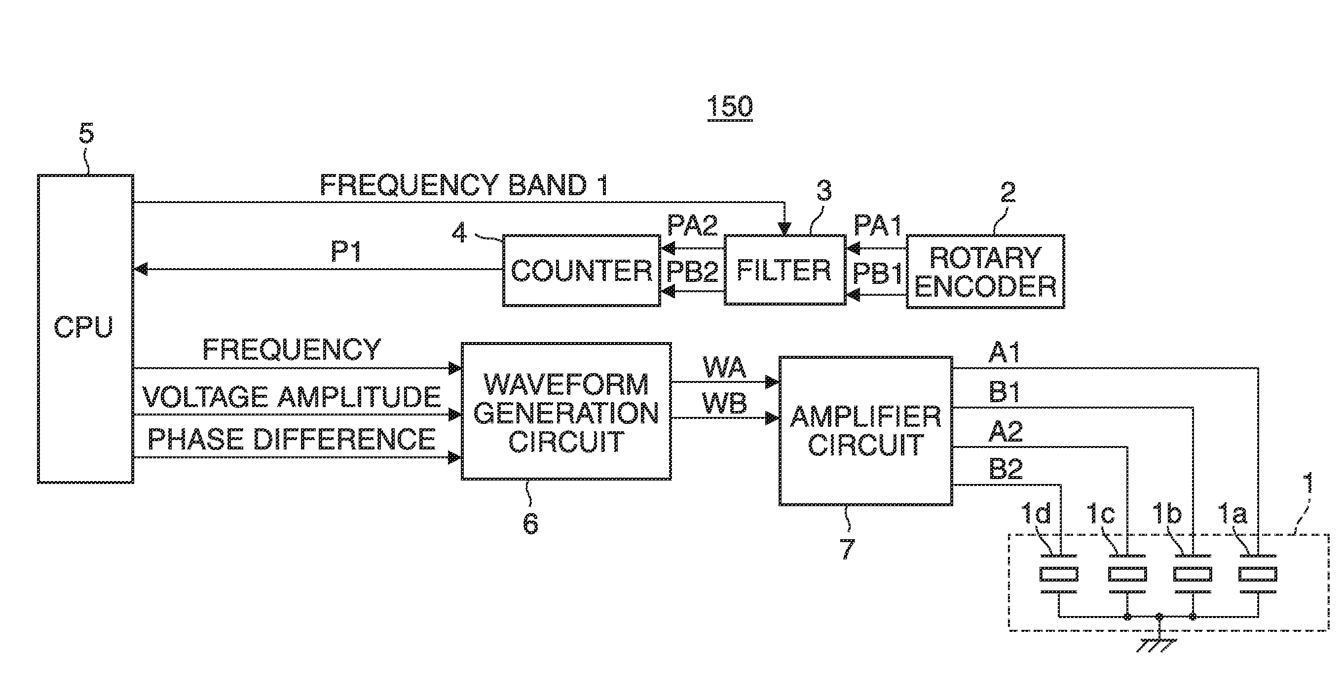
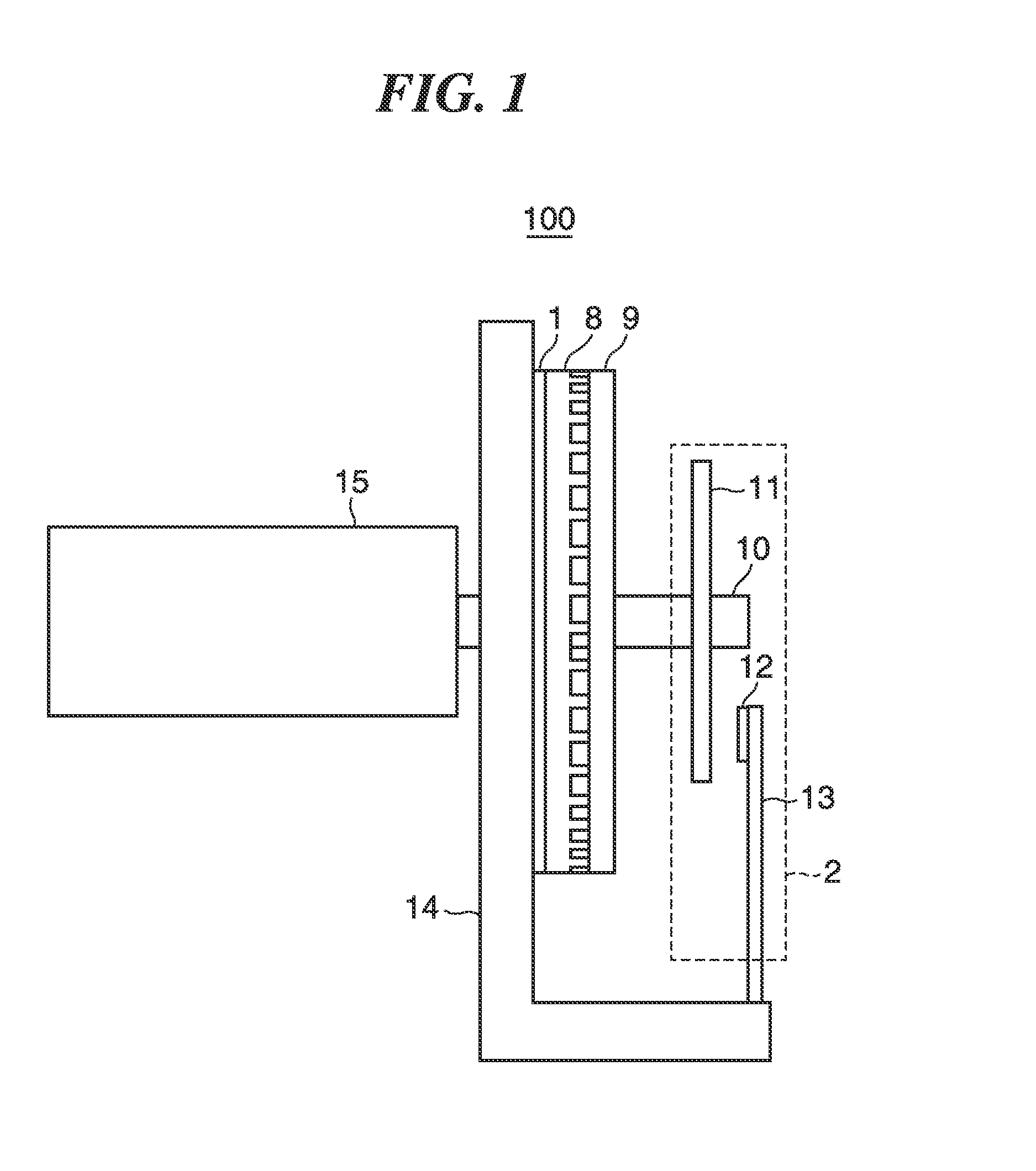
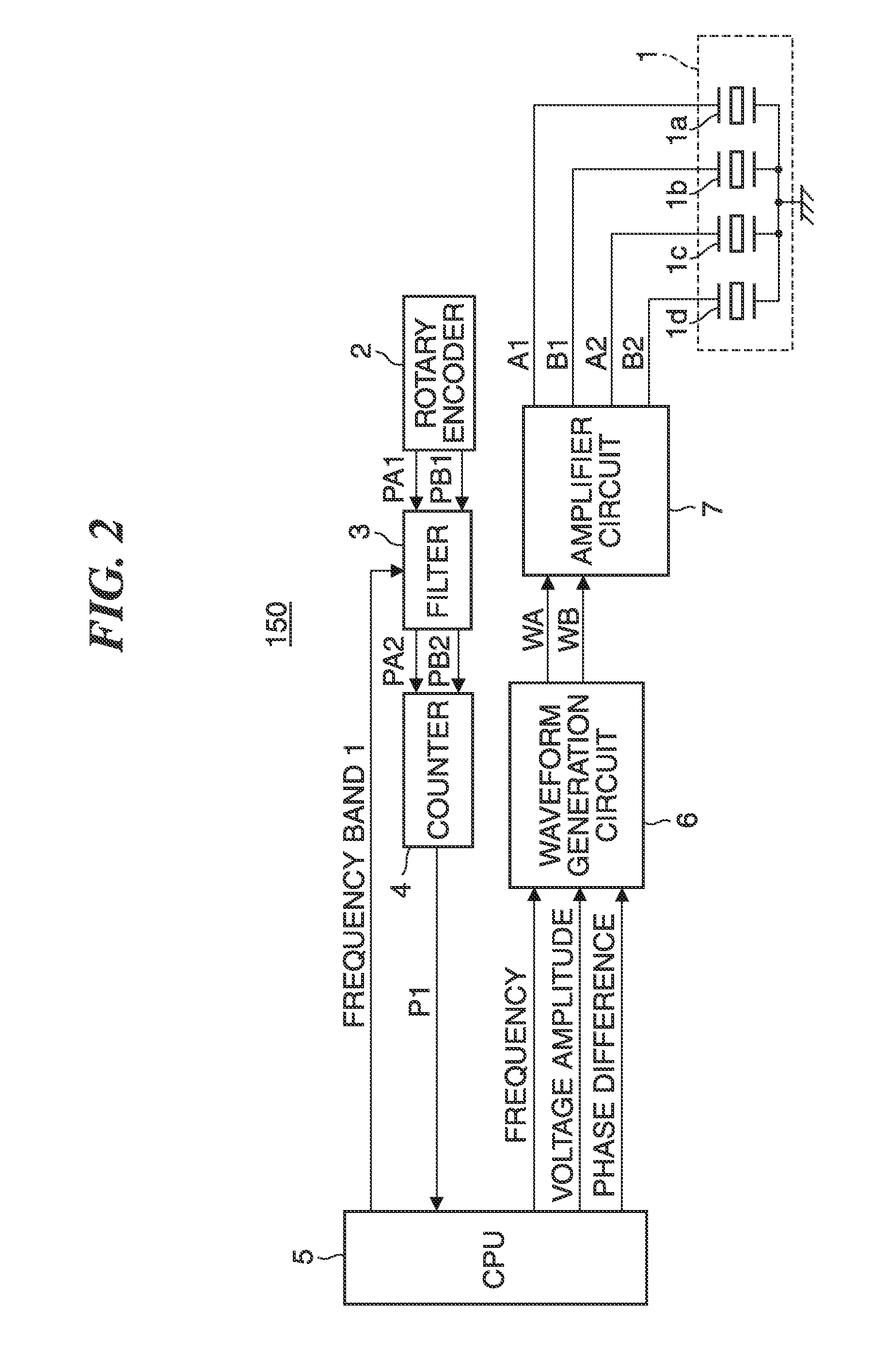
[0052]FIG. 1 is a schematic side view of a vibration actuator 100 as a target of driving control of a controller according to embodiments of the present invention. FIG. 2 is a schematic block diagram of a controller 150 according to the present invention, which controls the driving of the vibration actuator 100 shown in FIG. 1. The vibration actuator 100 shown in FIG. 1 and the controller 150 shown in FIG. 2 are components of the vibration type actuator apparatus according to the present invention.

[0053]The vibration actuator 100 includes an annular piezoelectric element 1, an annular elastic body 8, an annular driven element 9, an output shaft 10, and a support base 14. A rotary encoder 2 as a component of the controller 150 is mounted on the vibration actuator 100, and the rotary encoder 2 includes a disk-shaped optical scale 11, an optical sensor 12, and a circuit board 13.

[0054]The piezoelectric element 1 which is an electromechanical energy conversion element is bonded to the e...

second embodiment

[0123]FIG. 15 is a schematic block diagram of the controller, denoted by reference numeral 160, according to the In the present embodiment, the description is given assuming that a target of driving control of the controller 160 is the vibration actuator 100 shown in FIG. 1. The controller 160 differs from the controller 150 in that the filter 3 of the controller 150 is replaced by a first filter 3C, and a second filter 25 is provided which converts the position signal P1 input from the counter 4 to a position signal P2 and outputs the position signal P2 to the CPU 5. Therefore, the same components of the controller 160 as those of the controller 150 are denoted by the same reference numerals, and description thereof is omitted.

[0124]The first filter 3C included in the controller 160 is substantially the same as the filter 3 included in the controller 150. Therefore, the basic operation of the first filter 3C has already been described in the first embodiment, and hence description...

third embodiment

[0181]FIG. 23 is a schematic block diagram of a controller 170 according to the present invention. In the present embodiment, it is assumed that a target of driving control of the controller 170 is a vibration actuator having a structure in which the rotary encoder 2 provided in the vibration actuator 100 shown in FIG. 1 is replaced by an absolute encoder 37.

[0182]The controller 170 includes the CPU 5, the waveform generation circuit 6, the amplifier circuit 7, a filter 25F, the absolute encoder 37, and an interface circuit 38. The CPU 5, the waveform generation circuit 6, and the amplifier circuit 7 are the same as those included in the controller 150 according to the first embodiment (or the controller 160 according to the second embodiment), and hence description thereof is omitted. Further, the filter 25F is the same as the second filter 25 of the controller 160 according to the second embodiment, and hence description thereof is omitted.

[0183]The absolute encoder 37 outputs sig...


PUM


Abstract

A controller capable of improving position detection accuracy during the stopping of an actuator, and controlling the actuator with high stability and quick responsiveness during driving. A first position signal corresponding to an amount of relative movement between the actuator and said driven element is output to a filter, and the filter outputs a second position signal generated by attenuating signal components having frequencies except a specific frequency band. Driving and stopping of the actuator are controlled according to the second position signal. As the specific frequency band, a first frequency band is set in said filter during the driving of the actuator, and a second frequency band is set in said filter during the stopping of the actuator. The first frequency band and the second frequency band both include 0 Hz, and the second frequency band is narrower than the first frequency band.

Description

BACKGROUND OF THE INVENTION[0001]1. Field of the Invention[0002]The present invention relates to a vibration type actuator apparatus that is increased in position detection accuracy, a controller that controls the driving of an actuator of the vibration type actuator apparatus, and a medical system equipped with the vibration type actuator apparatus.[0003]2. Description of the Related Art[0004]As an example of an actuator that generates a driving force, there has been known a vibration actuator that brings a vibration element and a driven element into pressure contact with each other, and excites a vibration in the vibration element by applying an AC signal to thereby move the vibration element and the driven element relative to each other. The position control technique using the vibration actuator is used in various fields, such as an auto focus mechanism of an image pickup apparatus, a robot, a conveying equipment, a printing apparatus, and various manufacturing apparatuses. Of t...

Claims


Application Information

Patent Timeline
Patent Type & Authority Applications(United States)
IPC IPC(8): H02N2/14A61B5/00A61H23/02G05B1/01H02N2/10
CPCH02N2/142G05B1/01A61B5/0051A61H23/02H02N2/103A61H2201/1659A61H2201/5007A61H2201/5061A61H2201/5064A61H2201/5069A61H2201/5092A61B5/0263A61B5/055H02N2/106H02N2/163
Inventor KATAOKA, KENICHI
Owner CANON KK
Learn More