Intubating airway device

a technology of airway device and intubation tube, which is applied in the field of medical devices to achieve the effects of reducing the risk of regurgitation, improving the oesophageal seal, and reducing the risk of inflation of the stomach of the patien

Active Publication Date: 2016-11-17
INTERSURGICAL AG +1
View PDF2 Cites 10 Cited by
  • Summary
  • Abstract
  • Description
  • Claims
  • Application Information

AI Technical Summary

Benefits of technology

[0011]Preferably the intubating ramp is provided with a channel or groove. Preferably the channel or groove runs longitudinally along the full length of the intubating ramp from the first end to the second end of the longitudinal ramp. More preferably the intubating ramp is provided with a plurality of channels or grooves. The provision of the intubating ramp reduces the depth of the internal cavity of the laryngeal cuff, this means that should the device be sub-optimally inserted that there is risk that the airway of the patient could become partially occluded. The provision of the one or more channel(s) or groove(s) ensures the patency of the airflow through the airway device into the airway of the patient without compromising the effect of the ramp.
[0012]Preferably the tip of the laryngeal cuff is elongate. Preferably the tip of the laryngeal cuff is provided with a protrusion or bump on the back dorsal side thereof. The elongate nature of the tip of the laryngeal cuff along with the dorsal protrusion or bump both assist to provide an improved oesophageal seal when the airway device is in situ in the patient. By providing an improved oesophageal seal there is reduced risk of inflation of the stomach of the patient, and a reduced risk of regurgitation entering into the airway of the patient.
[0016]In one alternative the airway device further comprises a buccal cavity stabiliser located on or around the airway tube between the laryngeal cuff and the second end of the tube. The buccal cavity stabiliser, if provided, may be formed from the same material as the cuff or from a different material and assists in locating and maintaining the position of the device in use.
[0020]Preferably the laryngeal cuff and a front, ventral part of the buccal cavity stabiliser, if provided, are formed from a material of substantially the same Shore hardness. This simplifies construction and ensures that all portions of the device that come into firm contact with the patient's soft tissue are relatively soft.

Problems solved by technology

This often leads to the endotracheal tube, instead of entering the laryngeal inlet, sliding along the inside of the laryngeal cuff towards the tip of the device which can result in contact between the endotracheal tube and the larynx of the patient, and even insertion of the endotracheal tube into the oesophagus of the patient, both of which are undesirable.

Method used


Image

  • Intubating airway device
  • Intubating airway device
  • Intubating airway device

Examples


Embodiment Construction

[0033]Embodiments of the present invention are described below by way of example only. These examples represent the best ways of putting the invention into practice that are currently known to the applicant although they are not the only ways in which this could be achieved.

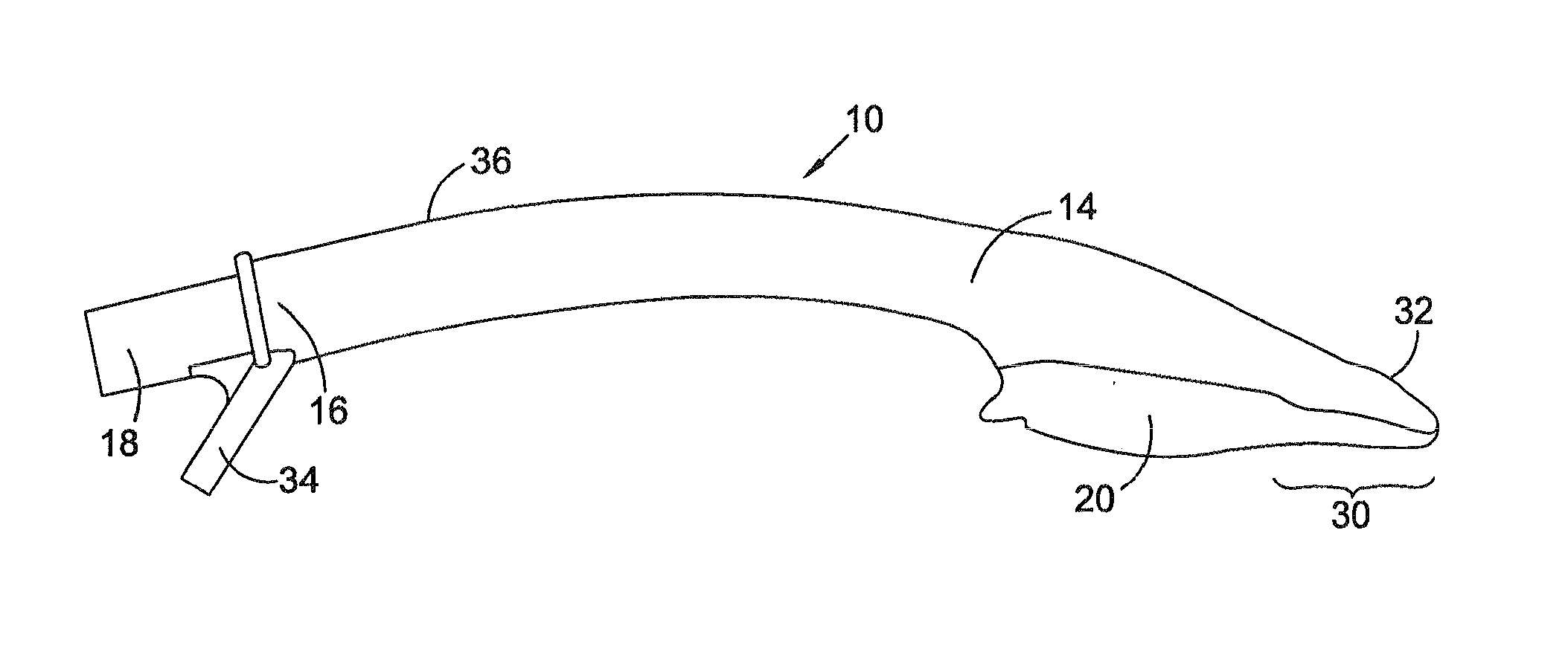
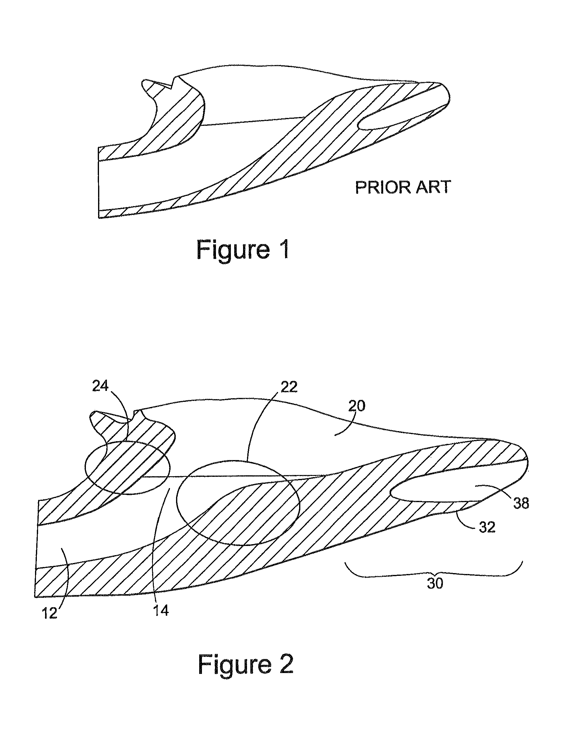
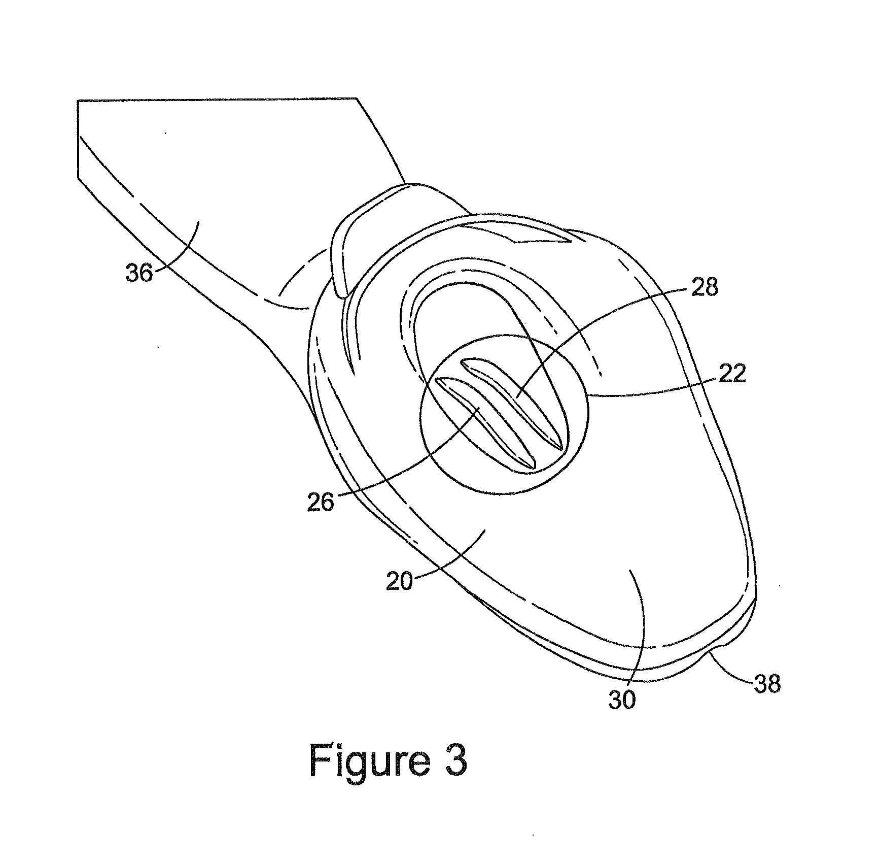
[0034]Referring to FIGS. 2 to 5, these illustrates an airway device 10 according to a first embodiment of the invention. The airway device 10 has an airway tube 12 having a first end 14 and a second end 16. The second end 16 optionally terminates in a 15 mm or other connector 18 suitable for connection to an anaesthetic breathing system of conventional type. Formed around the first end 14 of the airway tube is a laryngeal cuff 20. In the embodiment illustrated the laryngeal cuff 20 is non inflatable and is adapted in its shape and contours to correspond with the laryngeal inlet region of a patient.

[0035]The first end 14 of the airway tube 12 is also provided with an intubating ramp 22 configured to direct an endo...


PUM

PropertyMeasurementUnit
Shore hardnessaaaaaaaaaa

Abstract

An airway device for human or animal use includes an airway tube having a first end and a second end, the first end of which is surrounded by a laryngeal cuff configured to fit over the laryngeal inlet of a patient when in situ. The first end of the airway tube is provided with an intubating ramp configured to direct a tube inserted through the airway tube into the laryngeal inlet of the patient when in situ.

Description

FIELD OF THE INVENTION[0001]The present invention relates to medical devices and is applicable to laryngeal airway devices and to their methods of manufacture. It is particularly applicable to devices used in the administration of Oxygen and / or anaesthetic gases to a human or veterinary patient breathing spontaneously, for Intermittent Positive Pressure Ventilation (IPPV) during a surgical procedure or resuscitation and for intubating patients during such procedures.BACKGROUND TO THE INVENTION[0002]GB2393399 (Nasir) describes an airway device comprising an airway tube having a first end and a second end, the first end of which is surrounded by a non-inflatable laryngeal cuff which forms an anatomical fit over the laryngeal inlet of a patient and a buccal cavity stabiliser located on or around the airway tube between the laryngeal cuff and the second end of the tube, the buccal stabiliser being adapted to prevent rotational or side-to-side movement of the airway device in use.[0003]W...

Claims


Application Information

Patent Timeline
Patent Type & Authority Applications(United States)
IPC IPC(8): A61M16/04
CPCA61M16/0445A61M16/0488A61M16/0463A61M2250/00A61M16/0409A61M16/0438A61M16/0497A61M16/0402A61M16/0415A61M16/0431A61M16/0436A61M16/0486A61M16/04A61M16/0434B29C45/1676B29K2995/007B29L2031/753A61M2207/00A61M16/0443
Inventor NASIR, MUHAMMED ASLAMKEMP, JANE ELIZABETHMILLER, ANDREW NEIL
Owner INTERSURGICAL AG
Why Eureka
Try Eureka