Magnetic component

Active Publication Date: 2016-11-17
LITE ON ELECTRONICS (GUANGZHOU) LTD +1
View PDF11 Cites 7 Cited by
  • Summary
  • Abstract
  • Description
  • Claims
  • Application Information

AI Technical Summary

Benefits of technology

[0006]Accordingly, an objective of the instant disclosure is to provide a magnetic component, which can decrease the volume of the whole magnetic component without influencing conversion ef

Problems solved by technology

Because of the limitation of product process and height of the magnetic components, the magnetic components occupy bigger area in the circuit board.
However, th

Method used


Image

  • Magnetic component
  • Magnetic component
  • Magnetic component

Examples


Example

[0023]Reference will now be made in detail to the exemplary embodiments of the present disclosure, examples of which are illustrated in the accompanying drawings. Wherever possible, the same reference numbers are used in the drawings and the description to refer to the same or like parts.

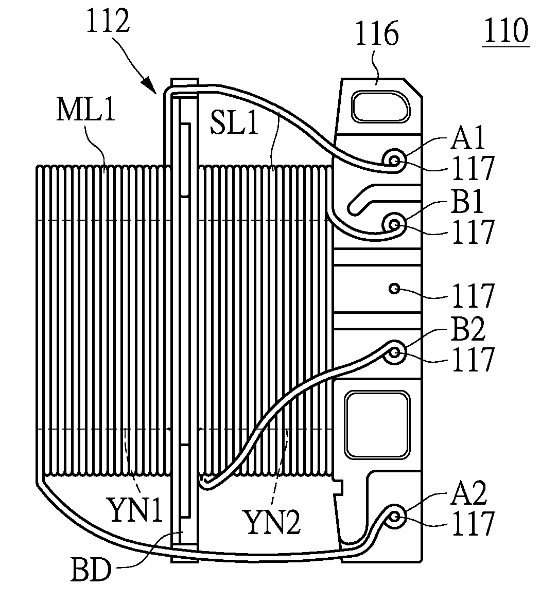
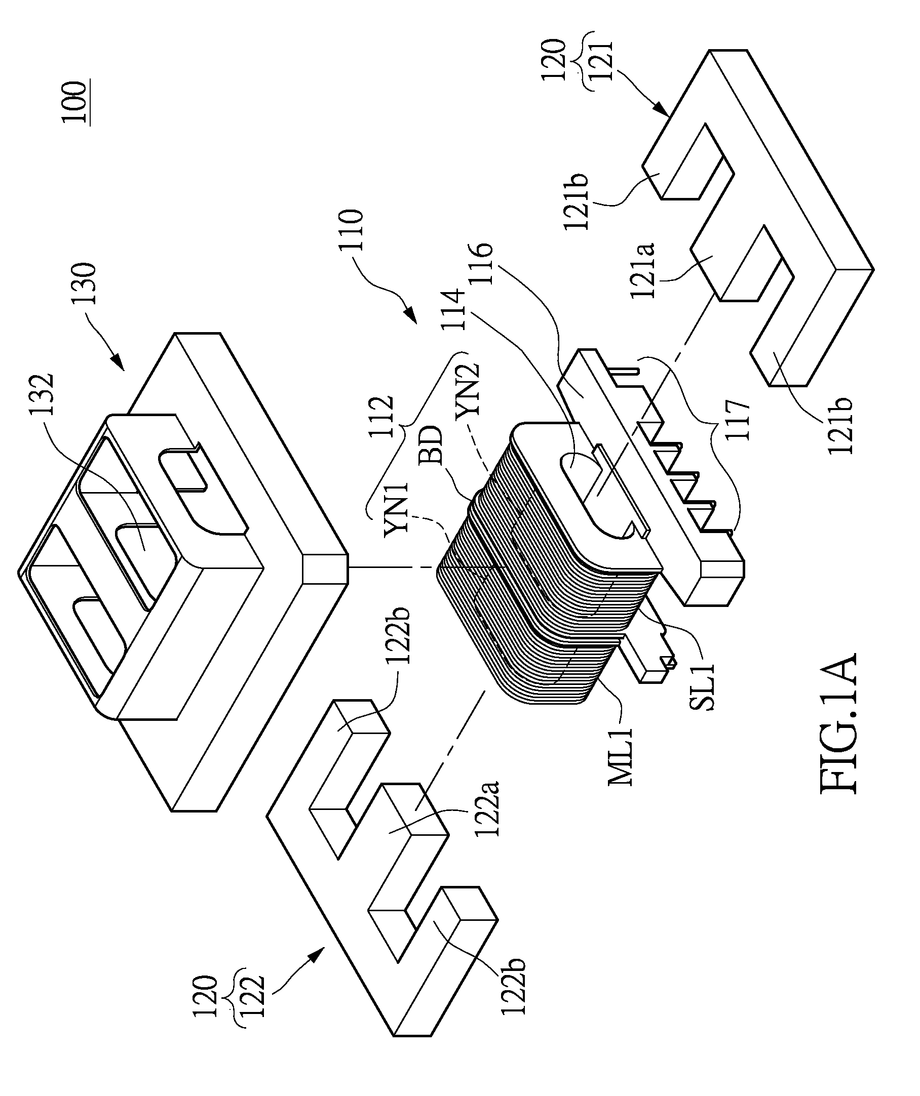
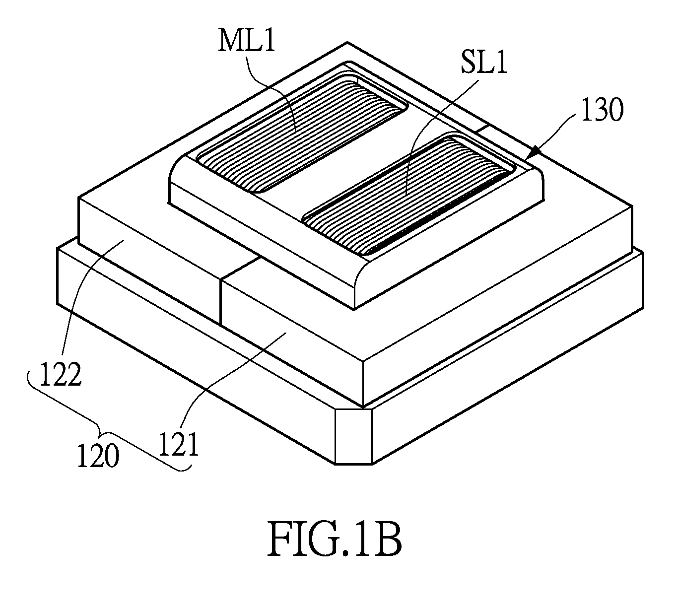
[0024]This embodiment provides a magnetic component having a primary winding and a secondary winding. At least one outlet terminal of the primary winding and at least one outlet terminal of the secondary winding are positioned at a same side. When the electronic device with the magnetic component wants to output the higher power, the secondary winding is laterally added in the magnetic component. Compared with the conventional magnetic component, the magnetic component of the present disclosure does not suffer from the limitation of product process and height, to achieve the needed current density outputted from the outlet terminal of the electronic device. The magnetic component provided in the exe...


PUM


Abstract

The present invention discloses a magnetic component and which includes a bobbin, a magnetic core assembly, a first winding, and a second winding. The bobbin has a main body, a channel, and a pin holder. The main body has a primary winding section and a secondary winding section. The channel penetrates the main body. The pin holder is extended from a side of the main body. The magnetic core assembly is partially disposed in the channel of the bobbin. The first winding and the second winding respectively have two outlet terminals. The first winding is wound around the primary winding section. The second winding is wound around the secondary winding section. Two outlet terminals of the first winding and two outlet terminals of the second winding are configured in the pin holder.

Description

BACKGROUND[0001]1. Technical Field[0002]The present disclosure relates to a magnetic component, in particular, to a magnetic component having a primary winding and a secondary winding, wherein the outlet terminals of the primary winding and those of the secondary winding are positioned at a same side.[0003]2. Description of Related Art[0004]Magnetic components are a necessary component in operating electrical equipment. Conventional electronic devices usually include many magnetic components, such as transformers. A transformer is a magnetic component capable of Electro-Magnetic Energy Conversion for adjusting the voltage into a suitable range.[0005]When the electronic device wants to output the higher power, it needs many magnetic components connected in parallel and the secondary winding needs to adopt the divided winding, so that the outlet terminal of the electronic device outputs the needed current density. Because of the limitation of product process and height of the magnetic...

Claims


Application Information

Patent Timeline
IPC IPC(8): H01F27/32H01F27/29
CPCH01F27/29H01F27/325H01F5/04H01F2005/043H01F27/2828
Inventor LI, TSAI-CHUNGLIAO, WEN-PINCHENG, CHOU-TINGLEE, HONG-CHIH
Owner LITE ON ELECTRONICS (GUANGZHOU) LTD
Why Eureka
Try Eureka