Improvements in or Relating to Generating Your Own Power

a technology of generating coils and laminates, which is applied in the direction of magnetic circuit rotating parts, magnetic circuit shapes/forms/construction, gymnastics exercise, etc., can solve the problems of reducing power consumption, reducing power consumption, and reducing power consumption, so as to improve the efficiency of generating power and reduce the cost. , the effect of reducing the number of users

Inactive Publication Date: 2016-11-17
GYO GYM
View PDF13 Cites 28 Cited by
  • Summary
  • Abstract
  • Description
  • Claims
  • Application Information

AI Technical Summary

Benefits of technology

[0069]Advantageously, a user may harvest power from active or passive movement which might, otherwise, be considered wasted or parasitic energy. The invention lends itself to those wishing to follow a ‘green’ lifestyle because components may be made from recycled materials and because low cost magnets are used. Printed coil laminates are quick and cheap to manufacture in contrast with wound coil technology.
[0070]Advantageously, an apparatus for generating power may be easily and / or discretely carried on the person of a user. Alternatively, it could be located in a hand-held item, such as a briefcase, or rucksack. Alternatively, it could be incorporated into a mobile electronic device, for example an mp3 player, tablet PC (personal computer) or mobile telephone. Further alternatively, it could be incorporated into an aftermarket casing for a mobile electronic device.
[0071]Advantageously, the printed coil laminate is flexible. As the backing and the ink are flexible, the laminate may flex in various planes. However, provision of a slit allows the laminate to additionally flex and form a circular or arc-like configuration.
[0072]Advantageously, the preferred embodiment seeks to make use of low cost materials by leveraging a large surface area available on rotating parts in relation to the relatively low amount of energy potentially harvestable. Conventional electrical generators tend to be designed with compactness as the main criteria. This leads to the use of rare earth magnets, compact windings, etc. The preferred embodiment utilizes the large surface area available to enable the use of larger conventional ferrite magnets, for example. Similarly, the preferred embodiment utilises the large surface area available to enable the use of foil-on-polyimide or foil-on-acetate, printed copper coil technology. With particular reference to bicycle or exercise variants of the invention, as a wheel thereof typically has a large surface area, it is a good location for lower cost magnetic technology, as there is no desire to make the wheel any smaller or more compact. The same can be said for coils used with that technology. Advantageously, a lattice-like formation of overlapping magnets and coil tracks optimises the amount of harvestable energy. In particular, as each individual magnet may move across a conductor at an angle of less than 90 degrees (sub-optimal) and potentially not fully move across the conductor, because in a reciprocating version the magnet may approach and leave the conductor without ever fully crossing it, the lattice formation enables the conductors—oriented at plus 45 degrees—and the magnets—oriented at minus 45 degrees—to achieve a preferred incidence angle of 90 degrees. Advantageously, a segmented conductor coil may be particularly advantageous if more than one magnet or set of magnetic tracks will move relative to the conductor coil, as each segment may independently generate power—which might otherwise be negated or cancelled out by the movement of a different magnet or set of magnetic tracks if inducing flux in the same conductor (un-segmented) conductor.

Problems solved by technology

Issues and problems associated with these existing devices centre around the fact that they are only suitable for generating energy from relatively high frequency vibration of, say, greater than 50 Hz and the amount of energy generated is quite small.
Accordingly, these types of devices tend to only find applications for local (off grid) power generation e.g. in remote sensors that are located in an environment experiencing high frequency vibration.
However, in comparison to other portable electronic devices, watches are much smaller and have a lower power consumption.
Therefore, whilst this technology might suit watches, it is not suitable for powering larger drain electronic devices.
Typically, only a small amount of energy may be harvested from a device of this kind in relation to the relatively costly infrastructure for capturing, storing and / or offloading that energy.
Further, the device may further act as a damping force thereby reducing energy efficiency.
A major disadvantage of known systems is their cost.
The cost of components is relatively high in comparison to the value of the energy which can be harvested.
Obviously, it is likely to take some time to pay back capital expenditure on equipment before starting to save money.
Furthermore, neodymium (NdFeB) magnets are expensive and are considered a critical resource.
Whilst ferrite technology is older and less efficient, there are sometimes important reasons (cost being an example) as to why one might wish to use an inferior material.

Method used


Image

  • Improvements in or Relating to Generating Your Own Power
  • Improvements in or Relating to Generating Your Own Power
  • Improvements in or Relating to Generating Your Own Power

Examples


Embodiment Construction

[0088]A preferred embodiment of the present invention will now be described.

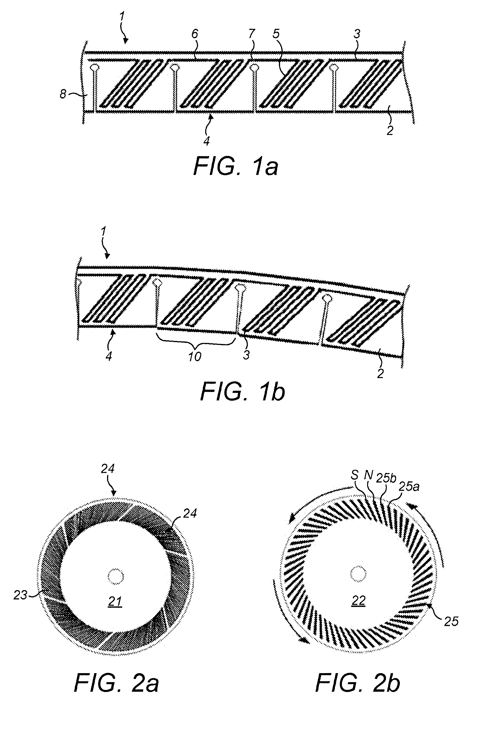
[0089]FIGS. 1a and 1b show a printed coil laminate, identified in general by reference 1. The laminate 1 includes a flexible backing 2 and a conductor 3. The flexible backing 2 is an insulating material, in this example KAPTON®—which is one example of a polyimide film commercially available and, of course, one could use a different insulating material. The conductor 3 is an ink which has been printed onto the flexible backing 2. The ink is a compound including copper which makes the ink both conductive and somewhat flexible. If additional flexibility is required, then the ink could also include beryllium. The ink has nominal thickness and a weight of approximately 310 g / m2 (2 oz / ft2). The conductor 3 is formed into a coil 4 through provision of a plurality of parallel conductive tracks 5 (of conductive ink). Each coil 4 is connected to a preceding coil 4 by a connector 6 and a succeeding coil 4 by a connecto...


PUM


Abstract

An exercise apparatus for generating electrical power is disclosed comprising a rotor comprising a flywheel comprising a plurality of alternatingly poled magnets arranged radially towards a circumference of the wheel in a circumferential, circular or arc-like configuration and a stator comprising a disc or annulus comprising one or more radially arranged coil units arranged to have a circumferential, circular or arc-like configuration, wherein the stator comprises a printed coil laminate comprising a sheet of insulator material and a printed conductor comprising conductive ink printed upon the sheet of insulator material, wherein the printed conductor is arranged to form a coil unit. The flywheel rotates, in use, relative to the disc to cause the magnets to move relative to the coil unit(s) and generate electrical power in the stator.

Description

CROSS-REFERENCE TO RELATED APPLICATION[0001]This application claims priority from and the benefit of United Kingdom patent application No. 1322478.7 filed on 18 Dec. 2013. The entire content of this application is incorporated herein by reference.BACKGROUND TO THE PRESENT INVENTION[0002]The present invention relates to a printed coil laminate, an apparatus for generating electrical power including a printed coil laminate, a portable apparatus for generating electrical power, a system for generating and harvesting your own electrical power, and a method for generating and harvesting your own electrical power. The preferred embodiment relates to harvesting energy from movement of a user—a by-product of either human exercise (active movement) or, for example, public transportation (passive movement). Active movement could be walking, running, aerobics, etc. Passive movement could be sitting on a train, or travelling in a car or on motorcycle. It is desired to store that energy so that ...

Claims


Application Information

Patent Timeline
Patent Type & Authority Applications(United States)
IPC IPC(8): H02K7/18H02K1/12H02K3/26A63B22/06H02K3/32H02K21/24A63B21/005A63B21/22H02K1/27H02K7/02
CPCH02K7/025H02K3/32H02K21/24A63B21/0055A63B21/0056H02K3/26A63B22/0605H02K7/1861H02K1/27H02K1/12A63B21/225H02K7/1876H02K11/0094H02K35/02
Inventor BICKERS, CHARLEYHOBBS, RICHARDPRESCOTT, MARTIN
Owner GYO GYM
Why Eureka
Try Eureka