Connector

A connector and pipeline technology, applied in the direction of adjustable connection, indirect heat exchanger, sealing surface connection, etc., can solve the problems of slow and sufficient temperature control, complex cost, limited and other problems, and achieve rapid manufacturing, cheap manufacturing, and space saving. Effect

Inactive Publication Date: 2020-04-17
NORMA GERMANY GMBH
View PDF10 Cites 0 Cited by
  • Summary
  • Abstract
  • Description
  • Claims
  • Application Information

AI Technical Summary

Problems solved by technology

[0005] The disadvantage of this is that the passing fluid can only be heated in the immediate vicinity of the heat conducting element, thereby only very slowly being able to adequately control the temperature of the entire solution
Furthermore, it is complex and costly to produce a connector with a heat-conducting element introduced into a pipe in a fluid-tight manner
[0006] In addition, in order to install an electric heating system on or in the fluid lines, additional space is required, for example, in the engine compartment, which is basically very limited

Method used


Image

  • Connector
  • Connector
  • Connector

Examples


Embodiment Construction

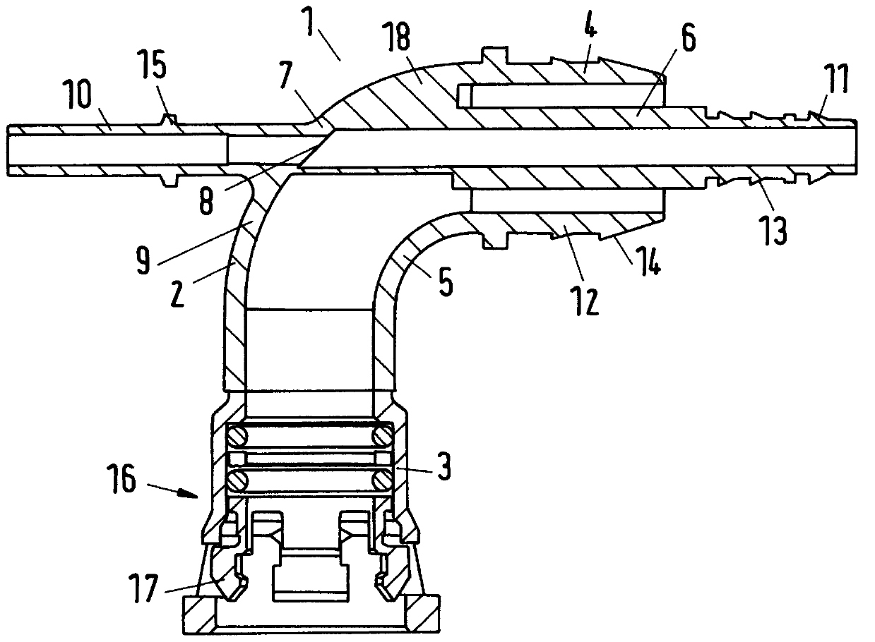
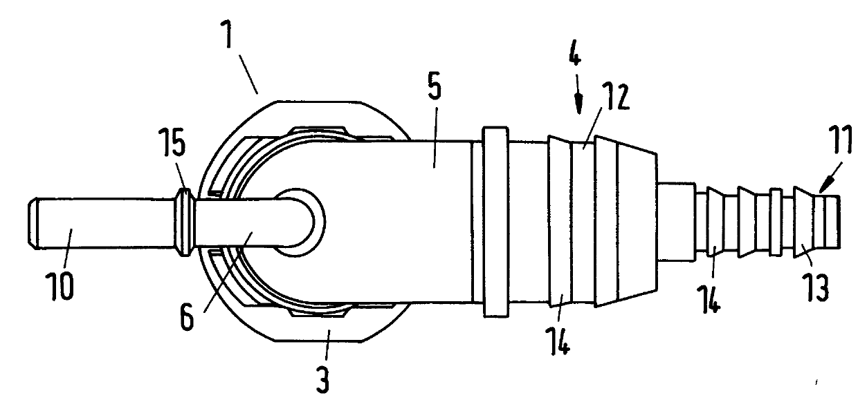
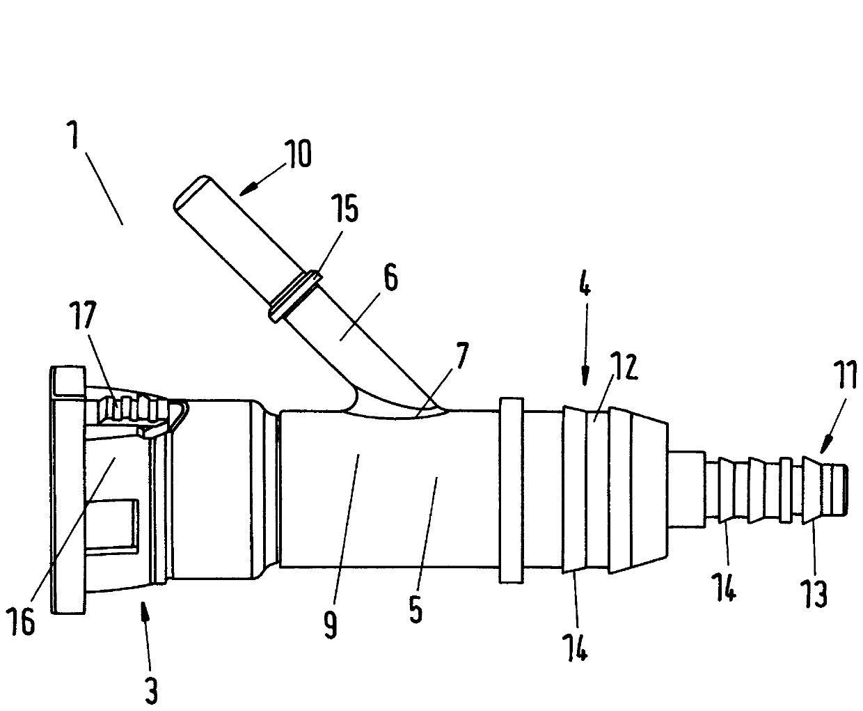
[0031] figure 1 A connector 1 according to the invention is shown, comprising a housing 2 . The housing 2 has a first end 3 and a second end 4 between which a first conduit 5 for a first fluid is arranged. A second conduit 6 for a second fluid is arranged at least partially within said first conduit 5 and exits coaxially through said second end 4 . The housing 2 has an outlet 7 with an outlet opening 8 through which the second conduit 6 leaves the housing 2 . The outlet portion 7 with the outlet opening 8 is arranged in a wall 9 of the first duct 5 .

[0032] Through the outlet opening 8 in the outlet section 7 the second conduit 6 for a second fluid is introduced into the first conduit 5 . A line-in-line system is thus formed. Here, the fluid systems of the first fluid and the second fluid are arranged separately from each other. The arrangement of the first conduit 5 and the second conduit 6 in the connector is realized such that they are completely fluid-tight and flow...


PUM

PropertyMeasurementUnit
fatigue bending timesaaaaaaaaaa

Abstract

The invention relates to a connector (1) for two fluid systems which are separated from one another in a liquid-tight manner. The connector comprises a housing (2) which has a first end (3) and a second end (4), a first channel (5) for the first fluid and formed between the first end (3) and the second end (4), and a second channel (6) for a second fluid and arranged at least partially inside thefirst channel (5), the second channel (6) passing coaxially through the second end (4). According to the invention, in the region of the first channel (5), the housing (2) has an outlet portion (7) having an outlet opening (8) through which the second channel (6) exits from the first channel (5).

Description

technical field [0001] The invention relates to a connector according to the preamble of claim 1 . Background technique [0002] Increasingly stringent requirements on fluid piping systems in terms of spatial arrangement and temperature control of conducting fluids require more compact solutions which can be produced in a simpler and more cost-effective manner. [0003] Especially in the aspect of using urea in diesel vehicles to reduce the emission of nitrogen oxides in the exhaust gas, it is necessary to control the temperature of the fluid since urea already crystallizes out at about -11°C. In order to control the temperature of the urea pipeline at lower external temperatures, it is known to provide an electric heating system arranged on or in the urea pipeline. [0004] An arrangement of this type is shown in EP 2 706 280 B1, in which a heat conducting element is provided which is introduced into a fluid line via a connector and thus makes it possible to control the te...

Claims


Application Information

Patent Timeline
Patent Type & Authority Applications(China)
IPC IPC(8): F16L9/18F01N3/20F16L11/20F16L39/00F16L43/00F28D7/10F28F1/00F16L53/32
CPCF01N3/2066F01N2530/20F01N2610/02F01N2610/10F01N2610/14F01N2610/1486F16L9/18F16L11/20F16L39/005F16L43/008F16L53/32Y02T10/12F16L19/025F16L27/0845F16L53/38
Inventor 乔安·克朗那
Owner NORMA GERMANY GMBH
Why Eureka
Try Eureka