Light Guiding Device

Active Publication Date: 2016-11-24
SMR PATENTS S A R L
View PDF2 Cites 63 Cited by
  • Summary
  • Abstract
  • Description
  • Claims
  • Application Information

AI Technical Summary

Benefits of technology

[0009]The light guiding device has a light incoupling side for coupling light from a light source into the light guiding device, a reflection side having a reflection layer for reflecting the incoupled light and a light outcoupling side. The light outcoupling side is preferably disposed essentially opposite the reflection side. The clearance between the reflection side and the light outcoupling side preferably basically decreases as the distance from the light incoupling side increases. This decrease of the clear

Problems solved by technology

In known light guiding devices, it has proven disadvantageous that the light deflected by the light guiding device is outcoupled relatively inhomogeneously over a surface to be illuminated.
As the line width of the pictogram increases,

Method used


Image

  • Light Guiding Device
  • Light Guiding Device
  • Light Guiding Device

Examples


Embodiment Construction

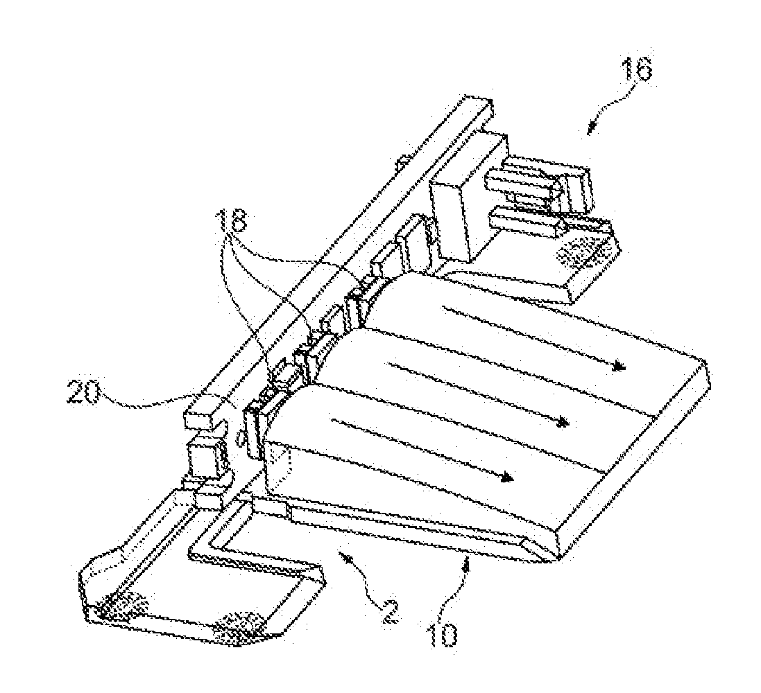
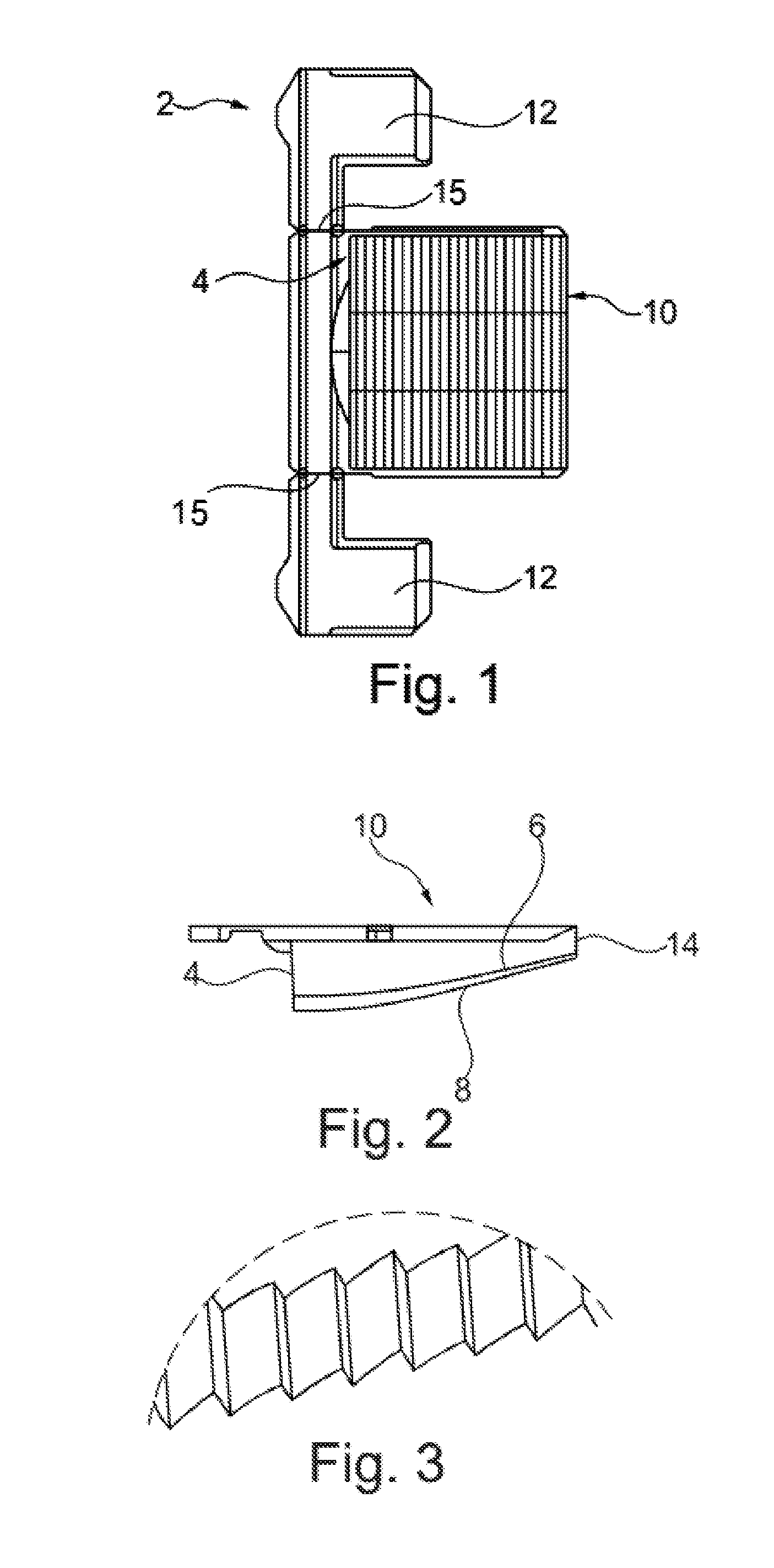
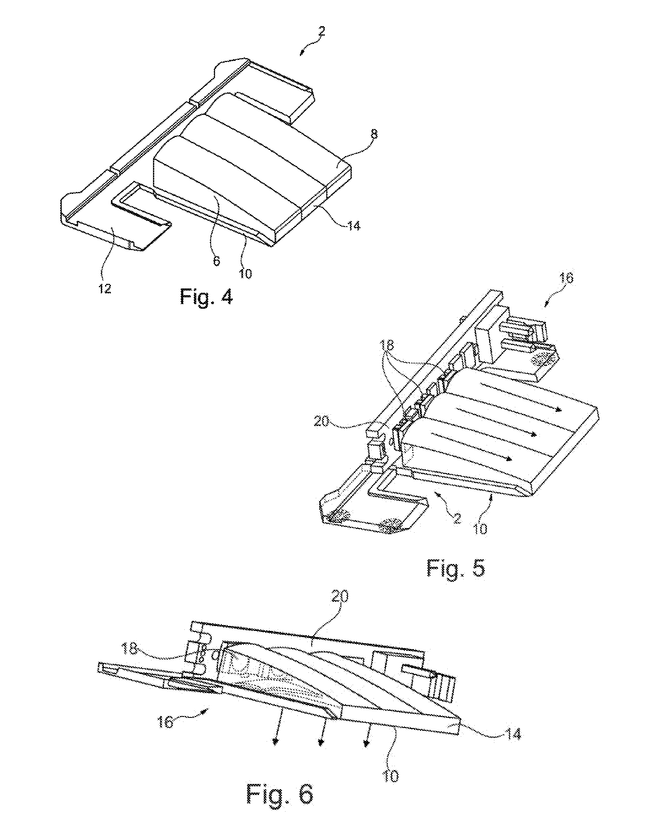
[0032]FIGS. 1 and 2 depict a top view of a light guiding device 2 having a light incoupling side 4, a reflection side 6, a reflection layer 8, and a light outcoupling side 10. In the top view of FIG. 1 the reflection side 6 is disposed under the light outcoupling side 10 and the reflection layer 8 is disposed under the reflection side 6. The light outcoupling side 10 is disposed opposite the reflection side 6 and therefore also opposite the reflection layer 8, so that reflected light reaches the light outcoupling side 10 as uniformly as possible. The clearance between the light outcoupling side 10 and the reflection side 6 and therefore also the reflection layer 8 decreases as the distance from the light incoupling side 4 increases. The light outcoupling side 10 and the reflection side 6 can thus converge continuously or form an edge 14 that can also have a reflection layer 8.

[0033]By way of example FIG. 1 moreover depicts two holding devices 12, which extend away from the light gui...


PUM


Abstract

A light guiding device for an illumination device, especially for a motor vehicle or an indicator device in a rearview device of a motor vehicle includes a light coupling side for incoupling light from a light source, a reflection side having a reflection layer; and a light outcoupling side, which is disposed generally opposite the reflection side. A clearance between the reflection side and the light outcoupling side generally decreases as the distance from the light incoupling side increases. The reflection side having the reflection layer is configured so that light arriving from the light incoupling side is deflected to the light outcoupling side. The reflection layer may be a paint or lacquer layer that is imprinted or evaporation-coated on the reflection side; and the having a white sheet on or next to the rejection side.

Description

CROSS-REFERENCE TO RELATED APPLICATIONS[0001]This application is a continuation-in-part patent application of United States Patent Application No. 15 / 000,733, filed Jan. 19, 2016 which claims the benefit of European Patent Application No. EP 15151604.4, filed Jan. 19, 2015. Thus, the subject nonprovisional application claims priority to European Patent Application No. EP 15151604.4, filed Jan. 19, 2015. The disclosures of both applications are incorporated herein by reference in their entirety.BACKGROUND OF THE INVENTION[0002]The invention relates to a light guiding device for an illumination device, such as a backlight or interior or exterior lighting, wherein incident light is deflected by reflection. The light guiding device can particularly be used in an indicator of a motor vehicle, in connection with a blind spot monitor in an outside mirror for example. The invention also relates to an illumination device, an outside mirror having such a light guiding device and a method for ...

Claims


Application Information

Patent Timeline
IPC IPC(8): F21S8/10B60Q1/52B60Q1/26
CPCF21S48/2243B60Q1/2665F21Y2115/10F21S48/2218B60Q1/525B60R1/1207G02B6/0046G02B6/0055G02B6/0078B60R1/06B60R2001/1215F21S43/14F21S43/255F21S43/245F21S43/249F21S43/315G02B6/00F21S43/239B60Q1/2607B60Q1/2696
Inventor KURSCHNER, NORBERTFRITZ, DANIELMEIER, EUGENERHART, VOLKERLITTLE, ANDREW BRIANWELFARE, HARRYEDNEY, STEPHEN
Owner SMR PATENTS S A R L
Why Eureka
Try Eureka