Driving unit

Active Publication Date: 2016-12-01
MITSUBA CORP
View PDF1 Cites 7 Cited by
  • Summary
  • Abstract
  • Description
  • Claims
  • Application Information

AI Technical Summary

Benefits of technology

[0013]According to the present invention, a ring gear of a planetary gear speed reducer is fixed to a casing provided with a fixed member fixed to a vehicle via a buffering member. Therefore, the driving unit can be reduced in size through adoption of a planetary gear speed reducer composed of a combination of spur gears, and the buffering member can suppr

Problems solved by technology

However, this driving unit encounters a problem that since it has: a speed reducer composed of a combination of spur gears; and a low-speed motor, low frequency vibrations are generated by the driving unit, and transmitted via a fixed member provided to the driving unit to a body pane

Method used


Image

  • Driving unit
  • Driving unit
  • Driving unit

Examples


Example

[0027]Hereinafter, the first embodiment of the present invention will be described in detail with reference to the drawings.

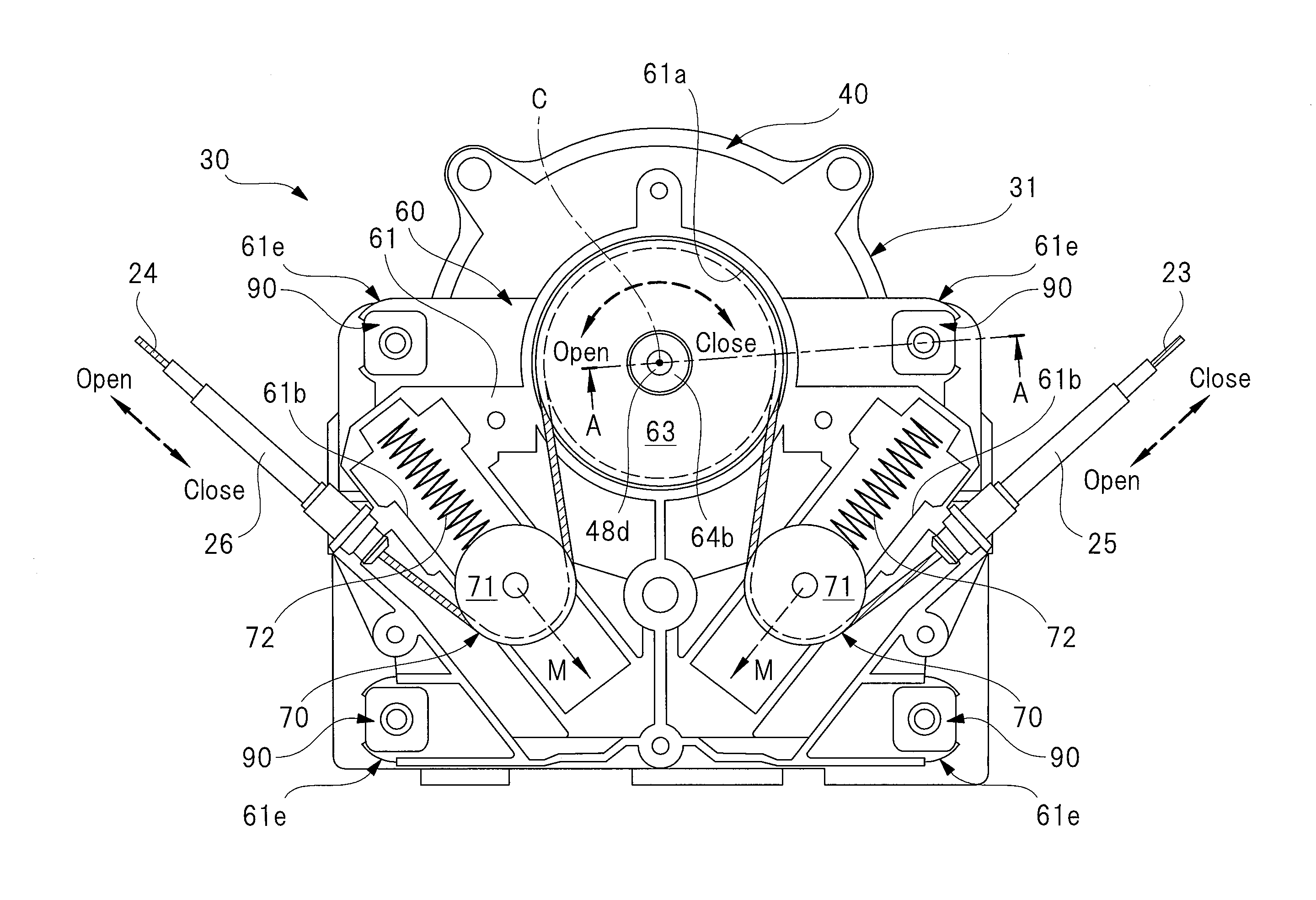
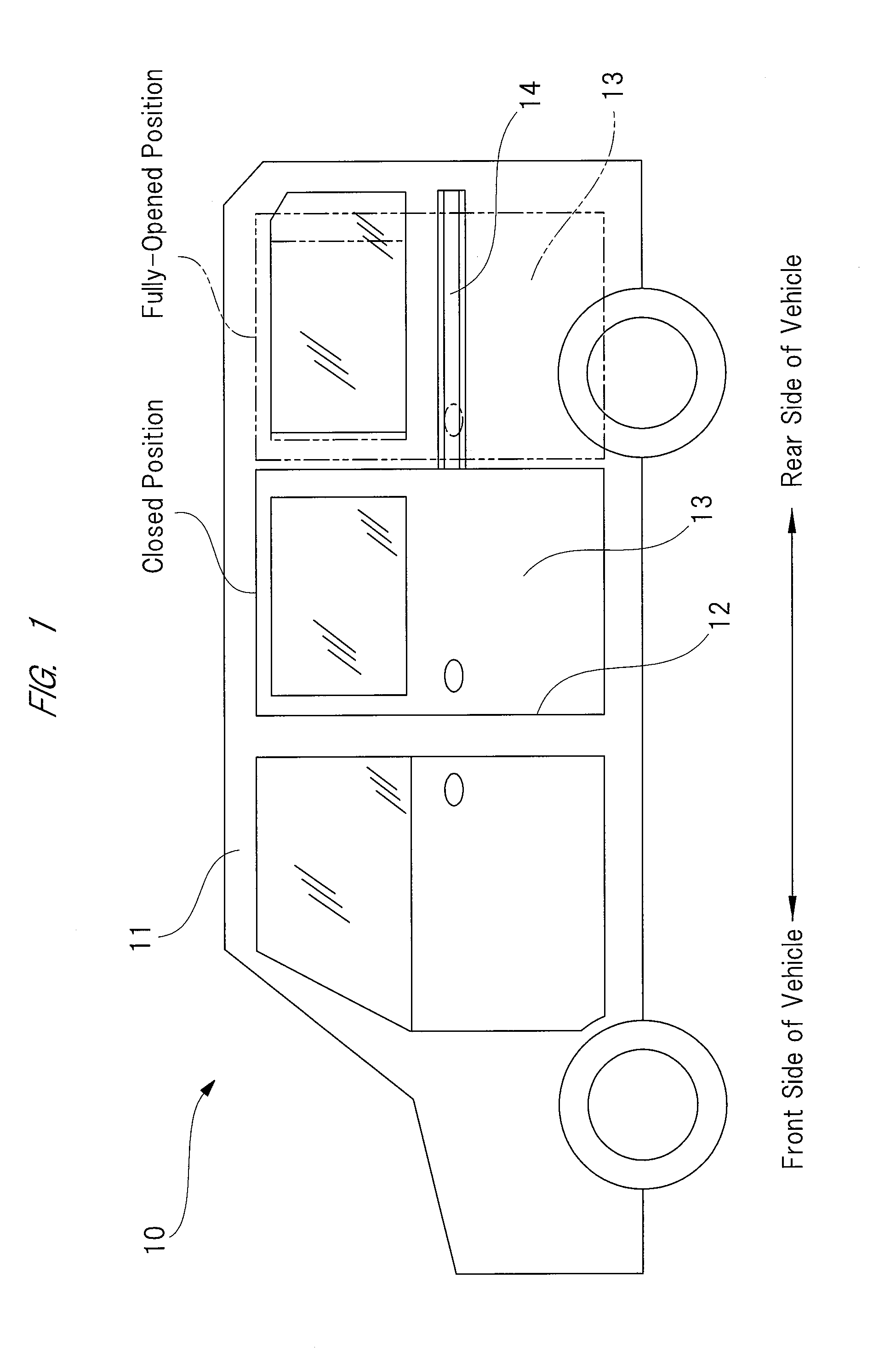
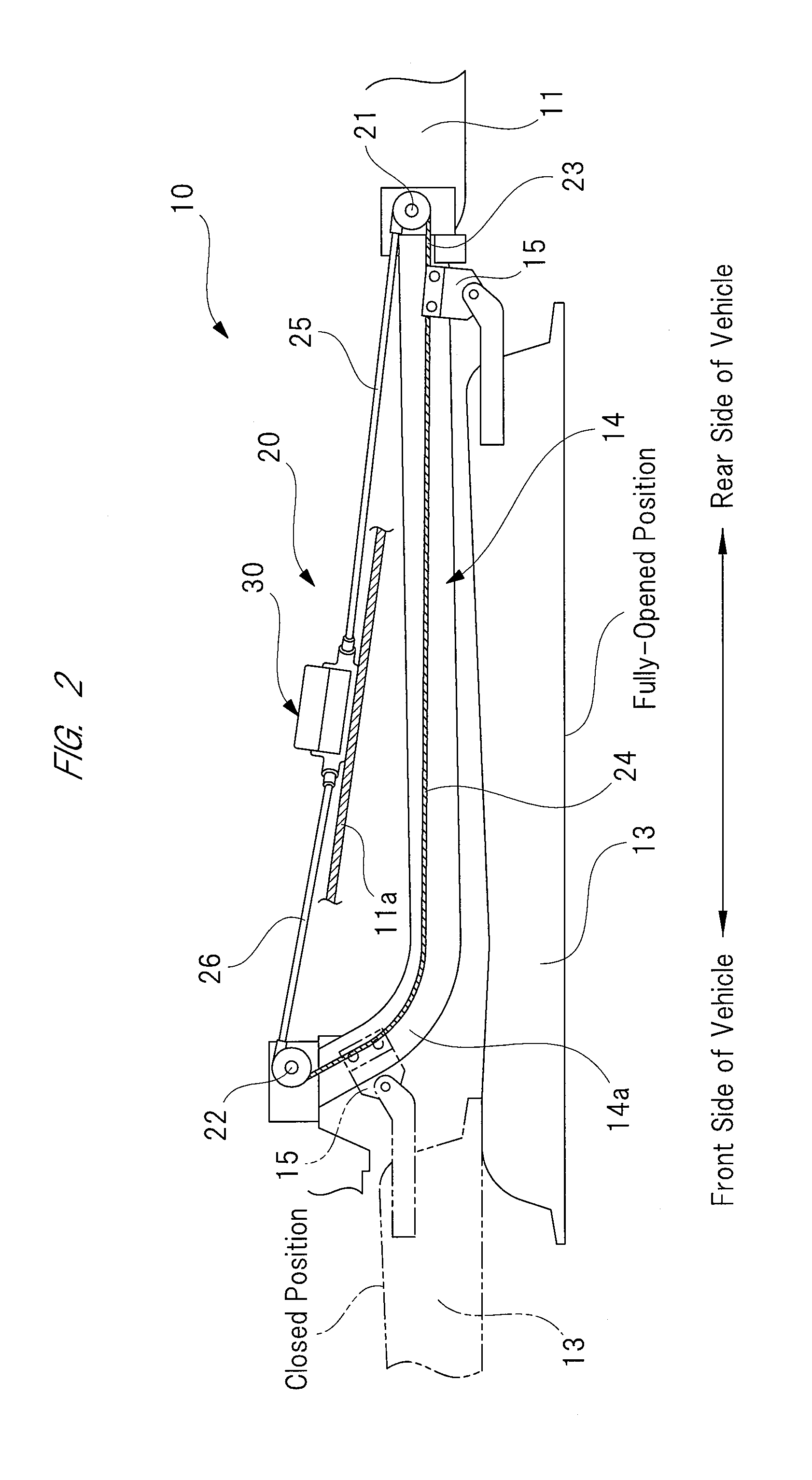
[0028]FIG. 1 is a side view showing a vehicle equipped with a driving unit according to a first embodiment, FIG. 2 is a plan view showing a mounting structure of a sliding door, FIG. 3 is a plan view showing a detailed structure of the driving unit, FIG. 4 is a partial sectional view taken along an A-A line in the plan view of FIG. 3, FIG. 5 is an exploded perspective view for explaining a fixing structure of a ring gear which is fixed to a motor case cover, FIG. 6 is an exploded perspective view for explaining a support structure of a drum housing case which supports the ring gear, FIG. 7 is an enlarged sectional view showing a part enclosed in a broken line circle “B” in FIG. 4, FIGS. 8A and 8B are perspective views each explaining a detailed structure of a fitting bush, and FIG. 9 is an explanatory view explaining a procedure of fitting the fitting bush to t...

Example

[0095]Next, the second embodiment of the present invention will be described in detail with reference to the drawings. In addition, elements and portions the same in configuration and function as those of the first embodiment are denoted by the same reference numbers as those of the first embodiment, and the detail explanations thereof are omitted.

[0096]FIG. 10 is a partial sectional view showing a driving unit according to a second embodiment, and corresponding to the partial sectional view of FIG. 4, FIG. 11 is an exploded perspective view for explaining a fixing structure of the ring gear which is fixed to the drum housing case, FIG. 12 is an exploded perspective view for explaining a support structure of a motor case cover which supports the ring gear, and FIG. 13 is an enlarged sectional view showing a part enclosed in a broken line circle “D” in FIG. 10.

[0097]As shown in FIGS. 10 and 13, a driving unit 100 according to the second embodiment is different from the driving unit 3...


PUM


Abstract

A ring gear (82) of a planetary gear speed reducer (80) is fixed to a casing (31) provided with a core metal (31) fixed to a vehicle panel via a rubber damper (92). Therefore, the driving unit can be reduced in size through adoption of a speed reducer (80) formed of gears (82) made of spur gears, and the rubber dumper (92) can suppress low frequency vibrations which are transmitted from the speed reducer (80) to the vehicle panel. Therefore, the vehicle body of the vehicle having a low characteristic frequency is prevented from resonating with the incoming low frequency vibrations to generate noises which are transmitted to the vehicle interior, and which give an occupant an unpleasant feeling.

Description

CROSS REFERENCE TO RELATED APPLICATION[0001]Applicant hereby claims foreign priority benefits under U.S.C. §119 from International Patent Application Serial No. PCT / JP2015 / 051901 filed on Jan. 23, 2015 and Japanese Patent Application No. 2014-012491 filed on Jan. 27, 2014, the contents of all of which are incorporated by reference herein.TECHNICAL FIELD[0002]The present invention relates to a driving unit for driving an opening and closing unit incorporated in a vehicle.BACKGROUND ART[0003]Conventionally, a vehicle such as station wagon and minivan is formed with a relatively-large opening which allows an occupant to easily get on and out of the vehicle and allows a baggage to be put in and taken out of the vehicle. Such an opening is opened and closed with a sliding door (opening and closing unit) provided with a roller assembly. Since the sliding door is heavy in weight, the vehicle equipped with the sliding door is provided with a sliding door opening and closing mechanism capabl...

Claims


Application Information

Patent Timeline
IPC IPC(8): F16H19/06E05D15/06H02K7/116F16H57/028F16H57/025H02K5/00E05F15/643F16H1/28
CPCF16H19/06F16H2057/02034E05D15/0621F16H1/28F16H57/028F16H57/025F16H19/0672H02K5/00H02K7/116E05Y2201/434E05Y2201/654E05Y2900/531E05Y2201/438E05Y2400/36F16H2019/0686E05F15/643B60J5/06E05Y2800/422E05F15/646E05Y2201/10E05Y2600/50H02K5/24F16H2057/02082F16H57/08
Inventor URANO, YOSHITAKAYOSHIDA, YASUSHISEKINE, YOSHITAKA
Owner MITSUBA CORP
Why Eureka
Try Eureka