Tank-in-tank container fill level indicator

a technology of fill level indicator and tank in tank container, which is applied in the direction of liquid handling, container discharging methods, instruments, etc., can solve the problems of inaccurate or broken pre-existing container fill level gauges, difficult to accurately predict an out-of-gas situation, and high consumption of dioxide, so as to achieve accurate measurement of liquid volume

Active Publication Date: 2016-12-01
TUTTLE NICHOLAS L
View PDF10 Cites 11 Cited by
  • Summary
  • Abstract
  • Description
  • Claims
  • Application Information

AI Technical Summary

Benefits of technology

[0011]In one aspect, a tank-in-tank fill level indicator, making use of noninvasive tank-in-tank measuring techniques, is provided. The housing and function of the indicator are optimized for ease of installation and automatic calibration. An electromechanical device, such as a vibration device, resonator, or exciter, vibrates the outer tank, preferably at its natural frequency of vibration, thereby inducing the vibration of the inner tank. A beating effect results from the interaction of the different resonant frequency vibrations of the two tanks. A vibration detection device, such as an accelerometer, detects the resultant beating effect of the two tanks' vibratio

Problems solved by technology

A problem often experienced by bulk-fill providers relates to the scheduling of bulk container filling.
Holidays or weekends can affect carbon dioxide consumption rates in an irregular manner, making it difficult to accurately predict an out-of-gas situation.
This problem is compounded by a common issue where the pre-existing container fill level gauges are broken or inaccurate, although the tanks themselves are otherwise fully functional.
A broken fill level gauge can occur when a given container reaches an empty, or nearly empty, state and the container's mechanical internal float is damaged, for example, from the remaining liquid freezing, rendering the fill level gauge inoperable.
Although invasive measuring devices, located within the volume of a container, are well known, the placement of an invasive measuring device within the container

Method used


Image

  • Tank-in-tank container fill level indicator
  • Tank-in-tank container fill level indicator
  • Tank-in-tank container fill level indicator

Examples


Embodiment Construction

[0030]For the purposes of promoting and understanding the principals of the invention, reference will now be made to one or more illustrative embodiments illustrated in the drawings and specific language will be used to describe the same.

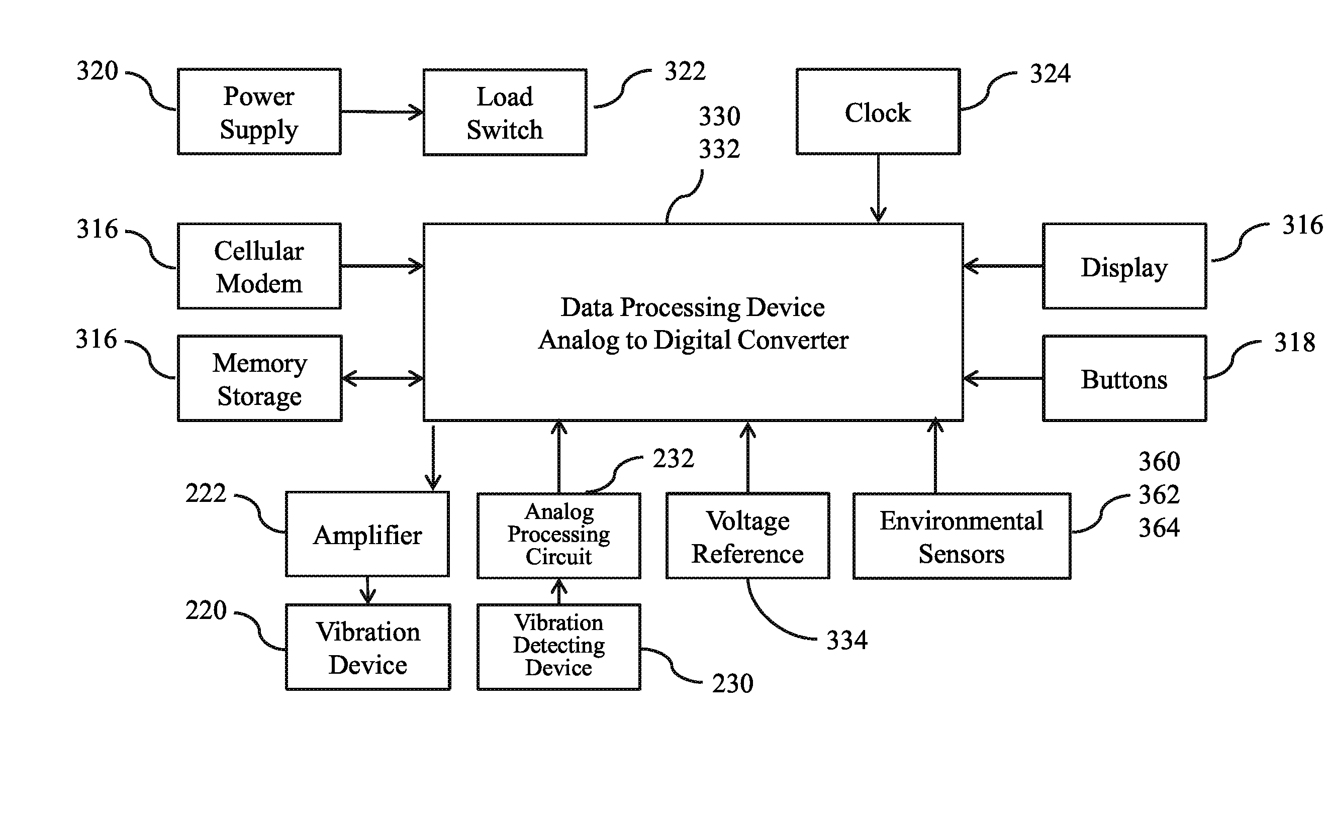
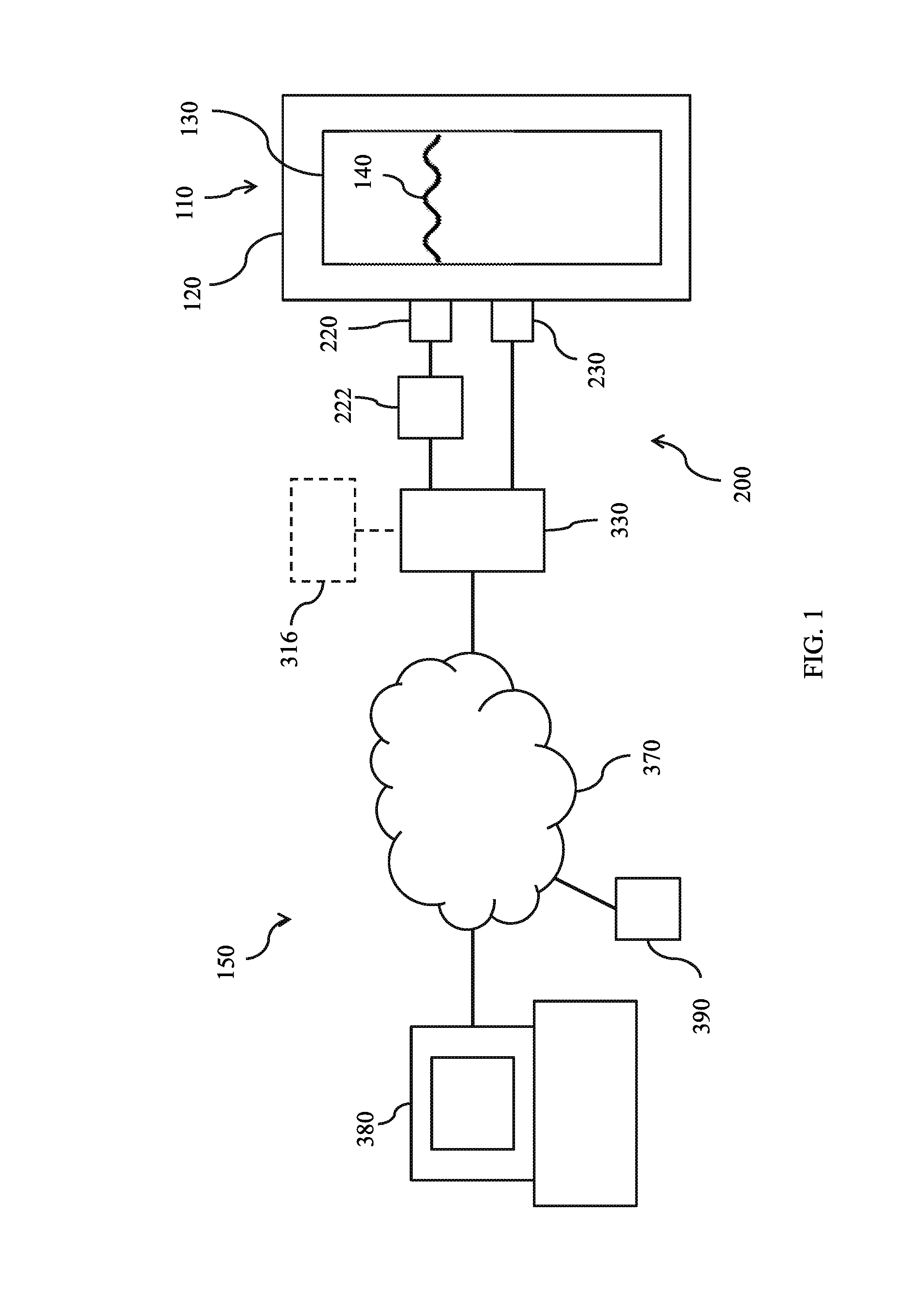
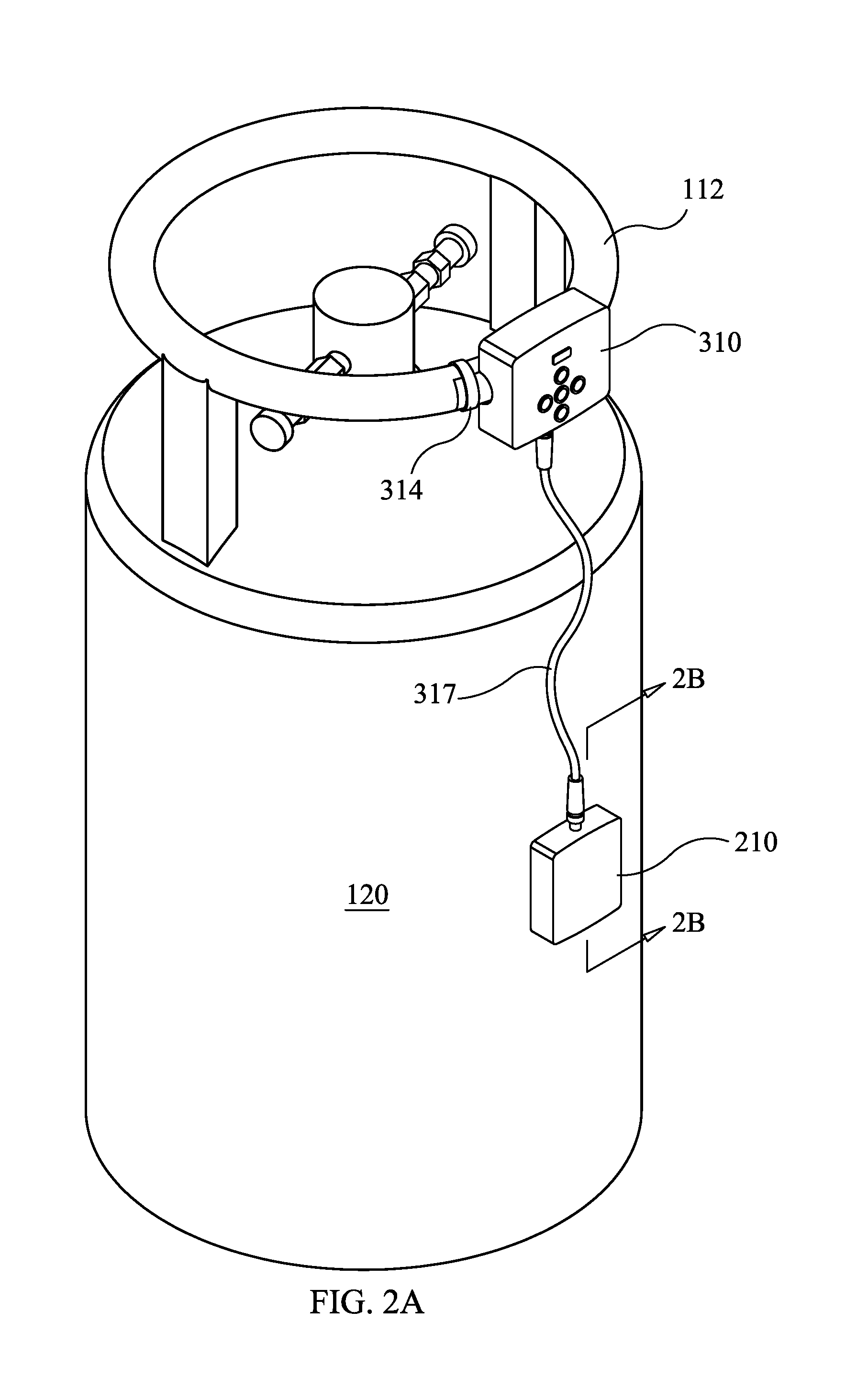
[0031]Tank-in-tank fill level indicator system 150, constructed according to the principles of this invention, is constructed for the purpose of enabling an accurate indication of liquid volume 140 within a tank-in-tank liquid container 110 in a non-invasive manner. When two or more sounds or vibrations are present having a frequency difference of less than about 20 or 30 Hz, a beat is formed at the difference frequency. The tank-in-tank fill indicator 200 associated with system 150 operates on the principle that the inner tank's resonant frequency 132 changes as the liquid volume 140 in the rigid inner tank 130 increases, and thus the number of beats present in the beat envelopes 143 per time period, resulting from the interaction of the outer tank...


PUM


Abstract

A tank-in-tank fill level indicator, making use of noninvasive tank-in-tank measuring techniques. A vibration device, such as an exciter or resonator, vibrates the outer tank at its natural frequency of vibration, thereby inducing the vibration of the inner tank and a beating effect as a result of the interaction of the vibrations of the two tanks. A vibration detection device, such as an accelerometer, detects the resultant beating effect of the two tanks' induced vibrations. A data processing device, such as a microcontroller, processes the detection data to obtain the liquid volume. A display, wired or wireless data transmission device, or combination thereof, is then used to provide tank or container fill-level information.

Description

CROSS-REFERENCE TO RELATED APPLICATIONS[0001]The application claims the benefit of U.S. Provisional Patent Application No. 62 / 167,376, filed May 28, 2015, and titled TANK-IN-TANK CONTAINER FILL LEVEL INDICATOR, and U.S. Provisional Patent Application No. 62 / 338,166, filed May 18, 2016, and titled TANK-IN-TANK CONTAINER FILL LEVEL INDICATOR, which are incorporated herein by reference.TECHNICAL FIELD[0002]The present disclosure relates generally to devices and methods for measuring the fill level of liquid or gas in a tank-in-tank container and, more particularly, to devices designed to measure the volume of liquid or gas in a tank-in-tank container in a noninvasive manner.BACKGROUND[0003]Restaurants and bars use gas, such as carbon dioxide, to carbonate fountain soft drinks and to preserve and push draught beer. Many restaurants have abandoned high-pressure compressed gas cylinders and are now using liquid bulk carbon dioxide as a safer, low-pressure alternative. Liquid bulk carbon d...

Claims


Application Information

Patent Timeline
IPC IPC(8): G01F23/296F17C13/02F17C1/12G01M3/00F17C1/04
CPCG01F23/2966G01M3/00F17C1/04H04L67/12F17C13/02F17C2221/013F17C1/12B67D1/008B67D1/0406B67D2001/0092F17C13/028F17C2201/0104F17C2201/032F17C2201/056F17C2203/0391F17C2203/0629F17C2205/058F17C2209/2163F17C2223/0153F17C2223/033F17C2250/032F17C2250/034F17C2250/0417F17C2250/0426F17C2250/0465F17C2250/0491F17C2250/0495F17C2260/024F17C2270/0745G06Q10/087F17C1/005F17C13/003G01F23/284
Inventor CROUSE, KENT ELDON
Owner TUTTLE NICHOLAS L
Why Eureka
Try Eureka