Ultrasound imaging system and ultrasound-based method for guiding a catheter

a technology of ultrasound and ultrasound, applied in the field of ultrasound-based method for guiding a catheter, can solve the problems of the catheter and the medical device are positioned in directions that are “out of plane, and it is difficult or impossible to tell

Inactive Publication Date: 2016-12-08
GENERAL ELECTRIC CO
View PDF0 Cites 45 Cited by
  • Summary
  • Abstract
  • Description
  • Claims
  • Application Information

AI Technical Summary

Problems solved by technology

While the 2D fluoroscopic X-ray image advantageously shows the position of the catheter in real-time, there are several disadvantages associated with relying primarily on a 2D fluoroscopic X-ray image for the guidance and ultimate placement of the implantable medical device in 3D space.
First, because the 2D fluoroscopic X-ray image is a 2D image from a single view direction, it is only possible to tell how the catheter and the medical device are positioned with respect to the plane of the 2D image.
In other words, it is difficult or impossible to tell how the catheter and medical device are positioned in directions that are “out-of-plane.” For example, if the 2D image represents an x-y plane, it is difficult or impossible to tell, based solely on a 2D image, how the catheter is positioned with respect to a z-direction perpendicular to the x-y plane.
However, X-rays are not as useful for imaging soft tissue.
Therefore, when relying on a 2D fluoroscopic X-ray image to guide a catheter and a medical device, the clinician does not have the benefit of detailed real-time information about the relative positioning of the catheter and medical device with respect to soft tissue structures within the patient.
For example, when the implantable medical device is a valve and the procedure includes replacing a mitral valve or an aortic valve, improper positioning of the implantable medical device (valve) may result in embolization of the device, coronary obstruction, or a paravalvular leak.
Third, relying on a 2D fluoroscopic X-ray image exposes both the patient and the clinician to X-ray dose the entire time the X-ray tube is turned on and emitting X-rays.

Method used


Image

  • Ultrasound imaging system and ultrasound-based method for guiding a catheter
  • Ultrasound imaging system and ultrasound-based method for guiding a catheter
  • Ultrasound imaging system and ultrasound-based method for guiding a catheter

Examples


Embodiment Construction

[0017]In the following detailed description, reference is made to the accompanying drawings that form a part hereof, and in which is shown by way of illustration specific embodiments that may be practiced. These embodiments are described in sufficient detail to enable those skilled in the art to practice the embodiments, and it is to be understood that other embodiments may be utilized and that logical, mechanical, electrical, and other changes may be made without departing from the scope of the embodiments. The following detailed description is, therefore, not to be taken as limiting the scope of the invention.

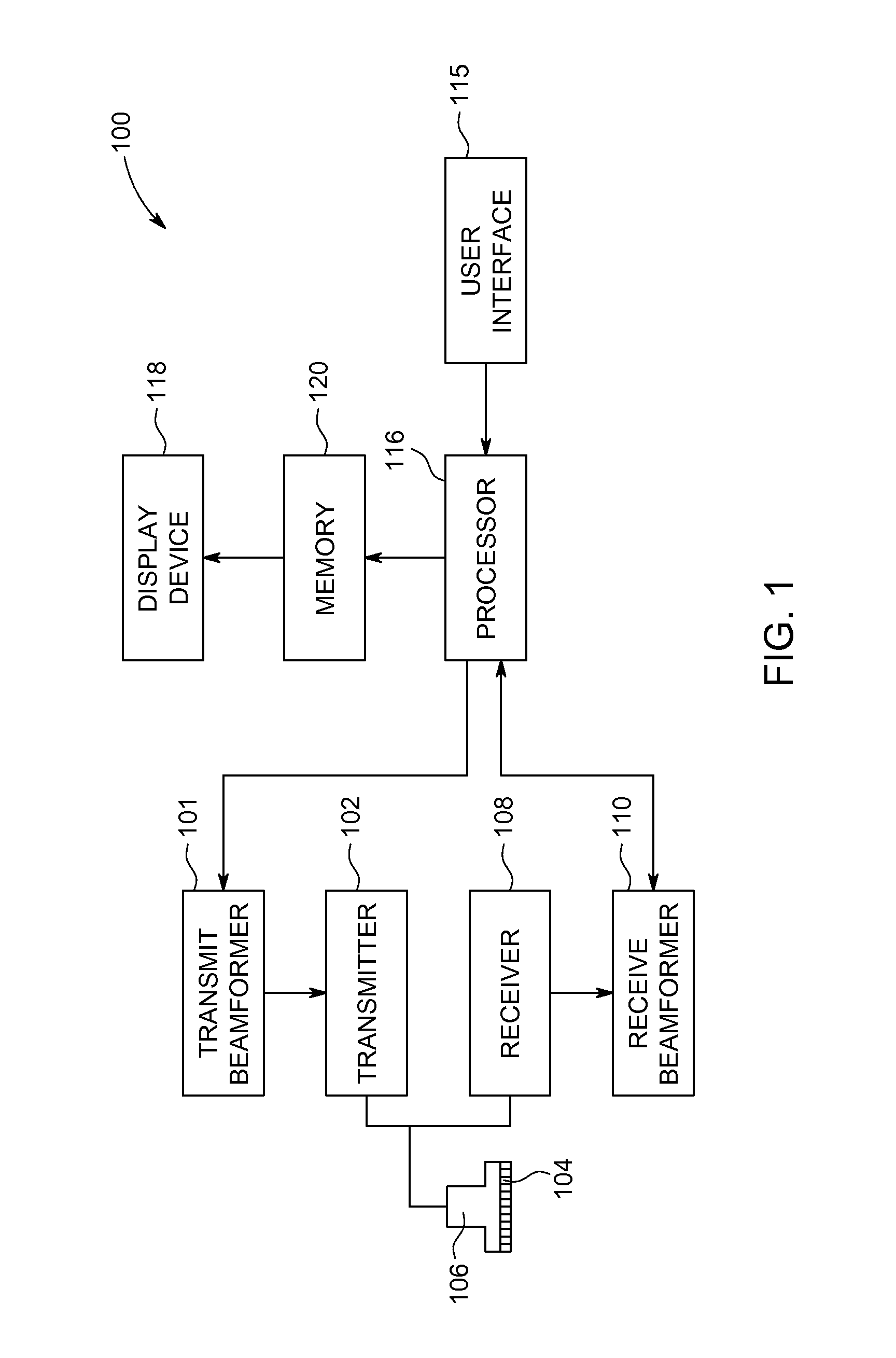
[0018]FIG. 1 is a schematic diagram of an ultrasound imaging system 100. The ultrasound imaging system 100 includes a transmit beamformer 101 and a transmitter 102 that drive elements 104 within a probe 106 to emit pulsed ultrasonic signals into a body (not shown). According to an embodiment, the probe 106 may be capable of acquiring real-time 3D ultrasound images. For exampl...


PUM


Abstract

An ultrasound imaging system and an ultrasound-based method for guiding a catheter during an interventional procedure include acquiring 3D ultrasound data, identifying a reference location, displaying an ultrasound image based on the 3D ultrasound data, and displaying a guideline superimposed on the ultrasound image, where the guideline represents the intended insertion path for the catheter with respect to the reference location.

Description

FIELD OF THE INVENTION[0001]This disclosure relates generally to an ultrasound imaging system and an ultrasound-based method for guiding a catheter during an interventional procedure.BACKGROUND OF THE INVENTION[0002]In order for an implantable medical device to have maximum efficacy with minimal risk for a given clinical indication, it is critical to guide and position the implantable medical device as accurately as possible. According to conventional techniques, many implantable medical devices are inserted via a catheter and guided with a 2D fluoroscopic X-ray image showing the real-time progress of the catheter through the patient's body. While the 2D fluoroscopic X-ray image advantageously shows the position of the catheter in real-time, there are several disadvantages associated with relying primarily on a 2D fluoroscopic X-ray image for the guidance and ultimate placement of the implantable medical device in 3D space.[0003]First, because the 2D fluoroscopic X-ray image is a 2D...

Claims


Application Information

Patent Timeline
Patent Type & Authority Applications(United States)
IPC IPC(8): A61B8/08A61B8/00A61B90/00A61B5/06
CPCA61B8/0841A61B5/062A61B2090/378A61B8/483A61B90/37A61B8/463A61B8/085A61B8/481A61B2034/107A61B2034/2051
Inventor HANSEN, GUNNARGERARD, OLIVIER
Owner GENERAL ELECTRIC CO
Why Eureka
Try Eureka