System and method for ventilating lungs

a technology of ventilating lungs and apparatus, which is applied in the field of apparatus and method for ventilating lungs, can solve the problems of inability to deliver a peep (positive end expiratory pressure) to the patient, inability to determine the volume of the patient, and inability to use volatile anesthetic agents haptically

Active Publication Date: 2016-12-08
GENERAL ELECTRIC CO
View PDF24 Cites 2 Cited by
  • Summary
  • Abstract
  • Description
  • Claims
  • Application Information

AI Technical Summary

Benefits of technology

[0013]The above-mentioned shortcomings, disadvantages and problems are addressed herein which will be understood by reading and understanding the following specification.

Problems solved by technology

Since volatile anesthetic agents are expensive and environmentally damaging to the atmospheric ozone layer, anesthesia machines have been developed to minimize the use of these gases.
The volume going to the patient, if any, is not possible to determine haptically by how much the bag is squeezed.
It is not possible to deliver a PEEP (Positive End Expiratory Pressure) to the patient with the APL valve.
Yielding from this, the Berner valve involves a safety problem related to every manual breath: Would the sensing of expiration fail, the valve remains closed resulting to unlimited breathing circuit and patient pressure increase.
This problem related to the difficult use of the method, which has limited its clinical use.
Problem of the described system is that at the time the manual bag compression is started, the breathing circuit pressure control valve is open, and the compression necessarily does not yield to the breathing circuit pressure and / or flow pattern expected from the predetermined control rule.

Method used


Image

  • System and method for ventilating lungs
  • System and method for ventilating lungs
  • System and method for ventilating lungs

Examples


Embodiment Construction

[0021]Specific embodiments are explained in the following detailed description making a reference to accompanying drawings. These detailed embodiments can naturally be modified and should not limit the scope of the invention as set forth in the claims.

[0022]The embodiments are directed to an arrangement and a method for a use in an intensified breathing, and for a use whenever anesthesia is being delivered to a subject.

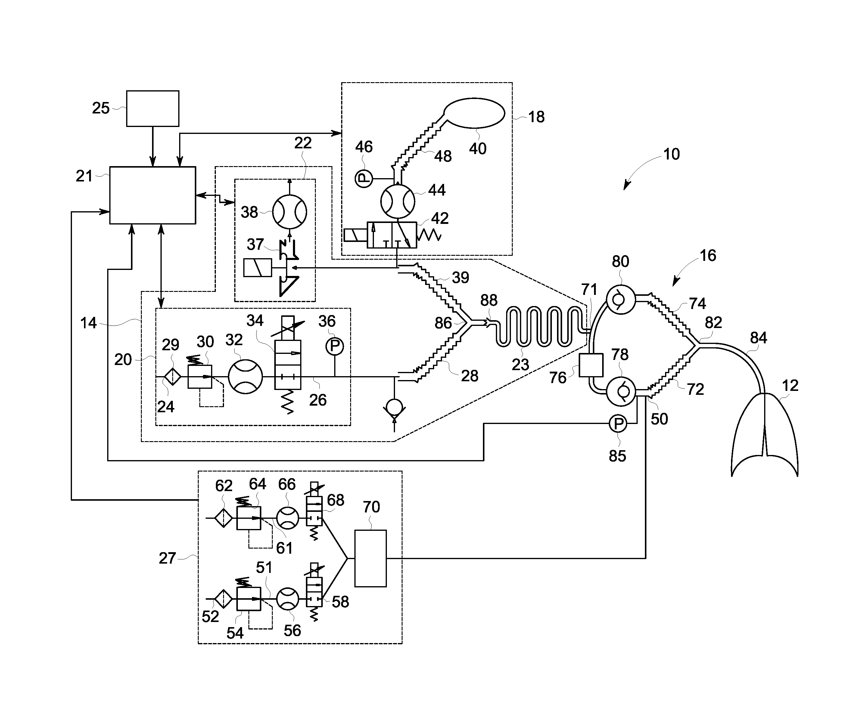
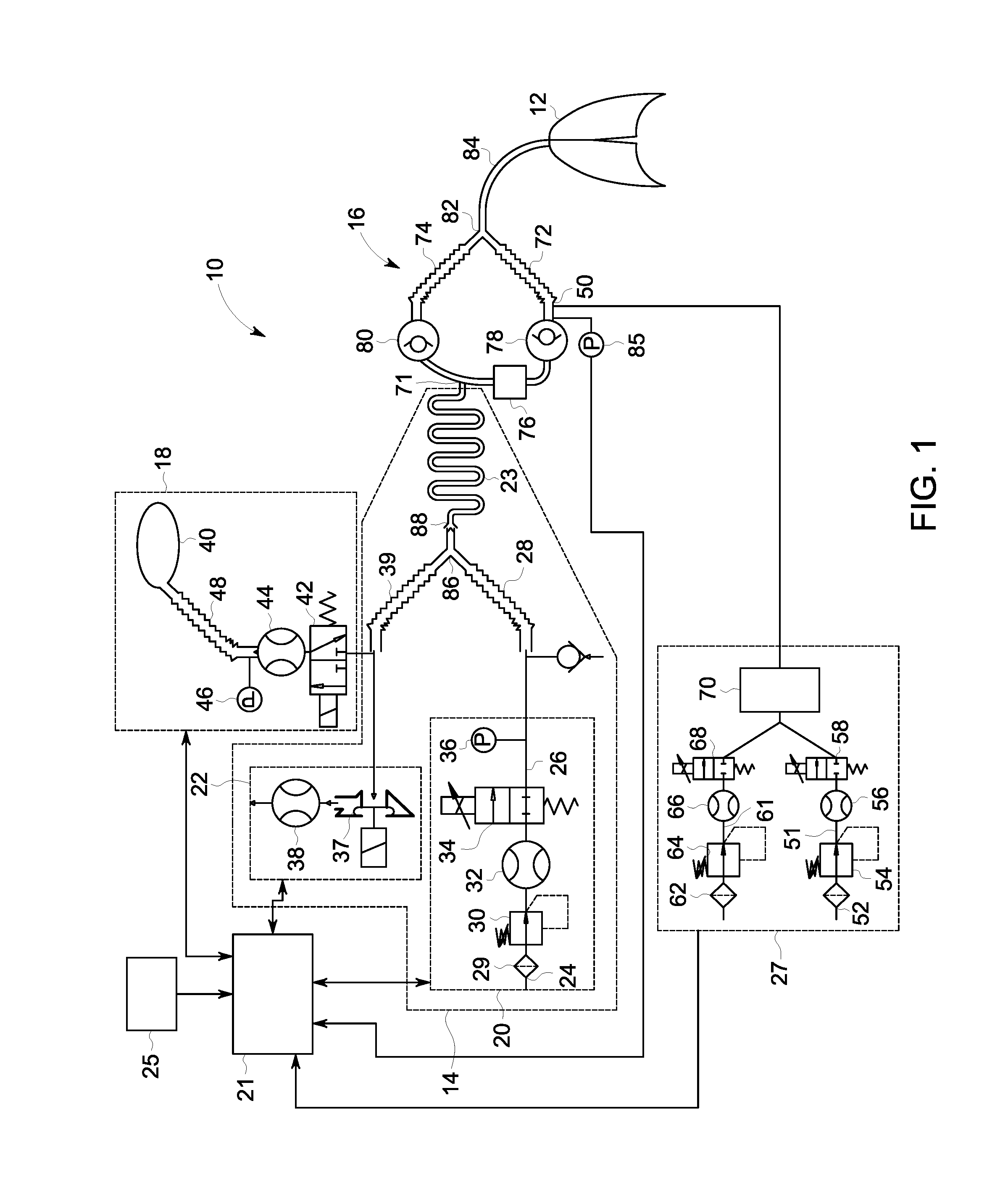
[0023]The arrangement 10 for providing an inspiration gas to the subject 12 utilizing a re-breathing system is shown in FIG. 1. The arrangement 10 comprises a machine ventilator circuit 14 for assisting breathing functions of the subject, a breathing circuit 16 for connecting lungs of the subject and the machine ventilator circuit 14 to exchange the gas in the lungs, a manual ventilation circuit 18 for enabling the manual ventilation of the subject and a control unit 21 for controlling an operation of the arrangement 10. The manual ventilation circuit 18 and the machi...


PUM


Abstract

A system for ventilating lungs of a subject is disclosed herein. The system includes a control unit configured to control operation of the system. The system also includes a machine ventilator circuit configured to assist the breathing functions of the subject, the machine ventilator circuit includes an inspiration delivery unit, and an expiration circuit. The system also includes a manual ventilation circuit comprising a manual bag guiding a gas from the manual bag wherein a gas flow is guided out from the manual bag to assist an inspiration phase, a gas flow is received to fill the manual bag during an expiration phase, and wherein the gas flow received to fill the manual bag during the expiration phase at least partially comprises the gas flow guided to assist the inspiration phase.

Description

BACKGROUND OF THE INVENTION[0001]This disclosure relates generally to an apparatus and method for ventilating lungs of a subject enabling to choose one of a machine ventilation for assisting breathing functions and a manual ventilation with a manual bag which can be compressed for an inspiration.[0002]Presently, anesthesia machines are optimized for delivering anesthesia to a patient using volatile anesthetic agent liquids. In such systems, the anesthetic agent is vaporized and mixed into the breathing gas stream in a controlled manner to provide a gas mixture for anesthetizing the patient for a surgical operation. The most common volatile anesthetic agents are halogenated hydrocarbon chains, such as halothane, enflurane, isoflurane, sevoflurane, and desflurane. Additionally, nitrous oxide (N2O) can be counted in this group of volatile anesthetic agents, although the high vapor pressure of nitrous oxide causes nitrous oxide to vaporize spontaneously in the high pressure gas cylinder...

Claims


Application Information

Patent Timeline
Patent Type & Authority Applications(United States)
IPC IPC(8): A61M16/00A61M16/12A61M16/10A61M16/20
CPCA61M16/0078A61M16/205A61M16/12A61M16/0081A61M2205/502A61M16/204A61M2016/0042A61M2016/0027A61M2016/0015A61M16/107
Inventor HAGGBLOM, TOM JAKOBHEINONEN, ERKKI PAAVO
Owner GENERAL ELECTRIC CO
Why Eureka
Try Eureka