Compression-release engine brake system for lost motion rocker arm assembly and method of operation thereof

a technology of compression release and engine, which is applied in the direction of valve details, valve arrangements, valve drives, etc., can solve the problems of engine overhead damage, reduced braking performance, and reduced exhaust stroke work, so as to avoid mechanical and thermal overload of the engine system, reduce the cost, and operate quietly

Active Publication Date: 2016-12-08
PACBRAKE
View PDF2 Cites 24 Cited by
  • Summary
  • Abstract
  • Description
  • Claims
  • Application Information

AI Technical Summary

Benefits of technology

[0020]Compression-release brake systems disclosed herein may be low cost and integrated into the overall engine design. Moreover, the compression-release brake systems may be lightweight, avoid mechanical and thermal overload of the engine system, exhibit quiet operation and high retarding power over the entire engine speed range where the engine brake is used.

Problems solved by technology

One problem with the conventional rocker arm brake system is that valve overlap at exhaust / intake is extended and thus braking performance decreased.
Moreover, a problem with opening a single valve is that exhaust / intake overlap is extended and valve opening by an exhaust bridge may be unbalanced during the initial normal exhaust lift and may result in engine overhead damage.
In other words, the extended valve overlap causes an undesired exhaust manifold air mass flow into the engine intake system, thus reducing exhaust stroke work and decreasing braking performance.

Method used


Image

  • Compression-release engine brake system for lost motion rocker arm assembly and method of operation thereof
  • Compression-release engine brake system for lost motion rocker arm assembly and method of operation thereof
  • Compression-release engine brake system for lost motion rocker arm assembly and method of operation thereof

Examples


first embodiment

[0190]FIGS. 21-31B illustrate a fifth exemplary embodiment of a compression-release brake system generally designated by reference numeral 512. Components that are unchanged from the above-described embodiments are labeled with the same reference numerals. Components of the system 512 corresponding to components of the first embodiment are designated by the same reference numerals as used in FIGS. 1-12 but in the 500 series.

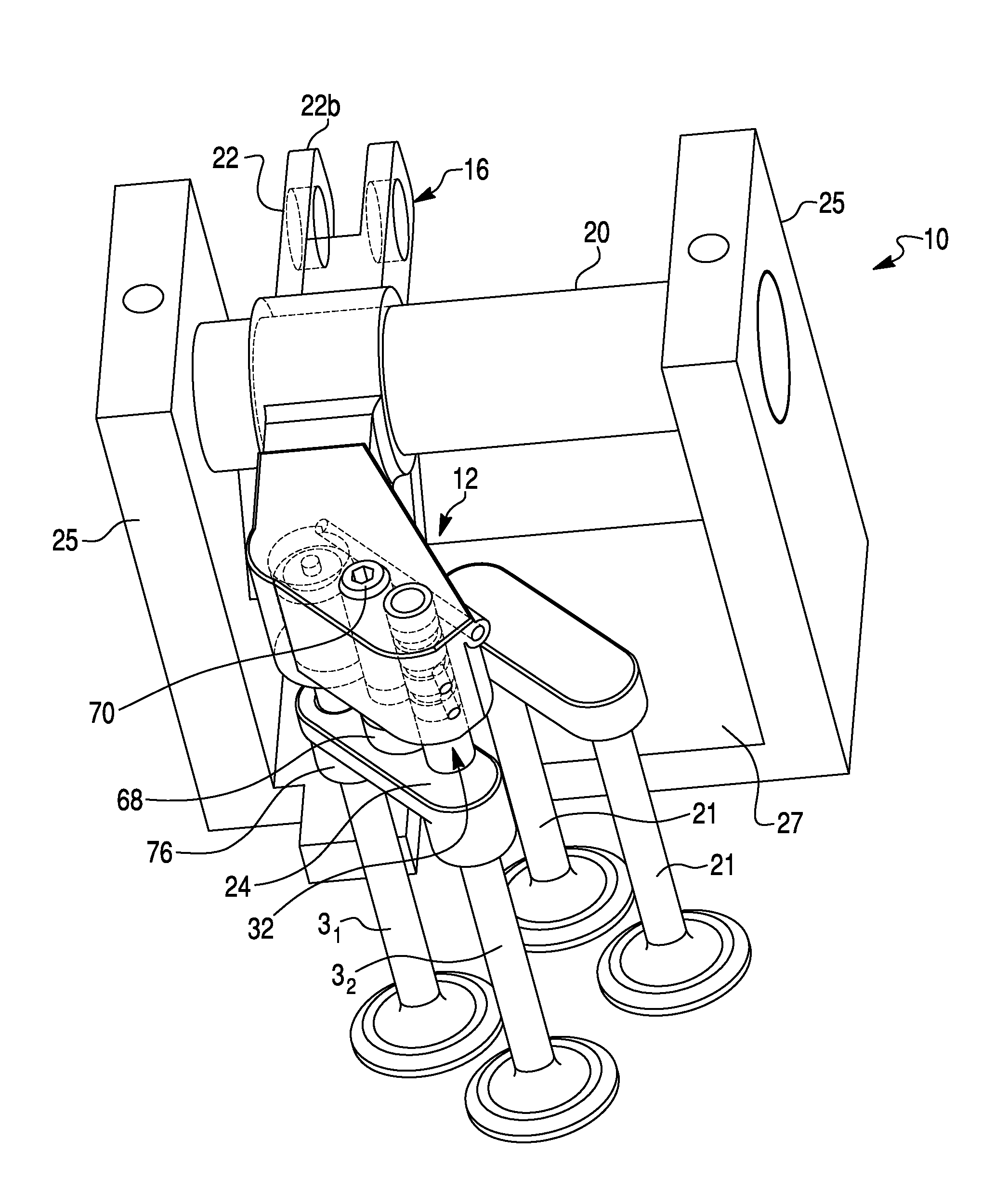
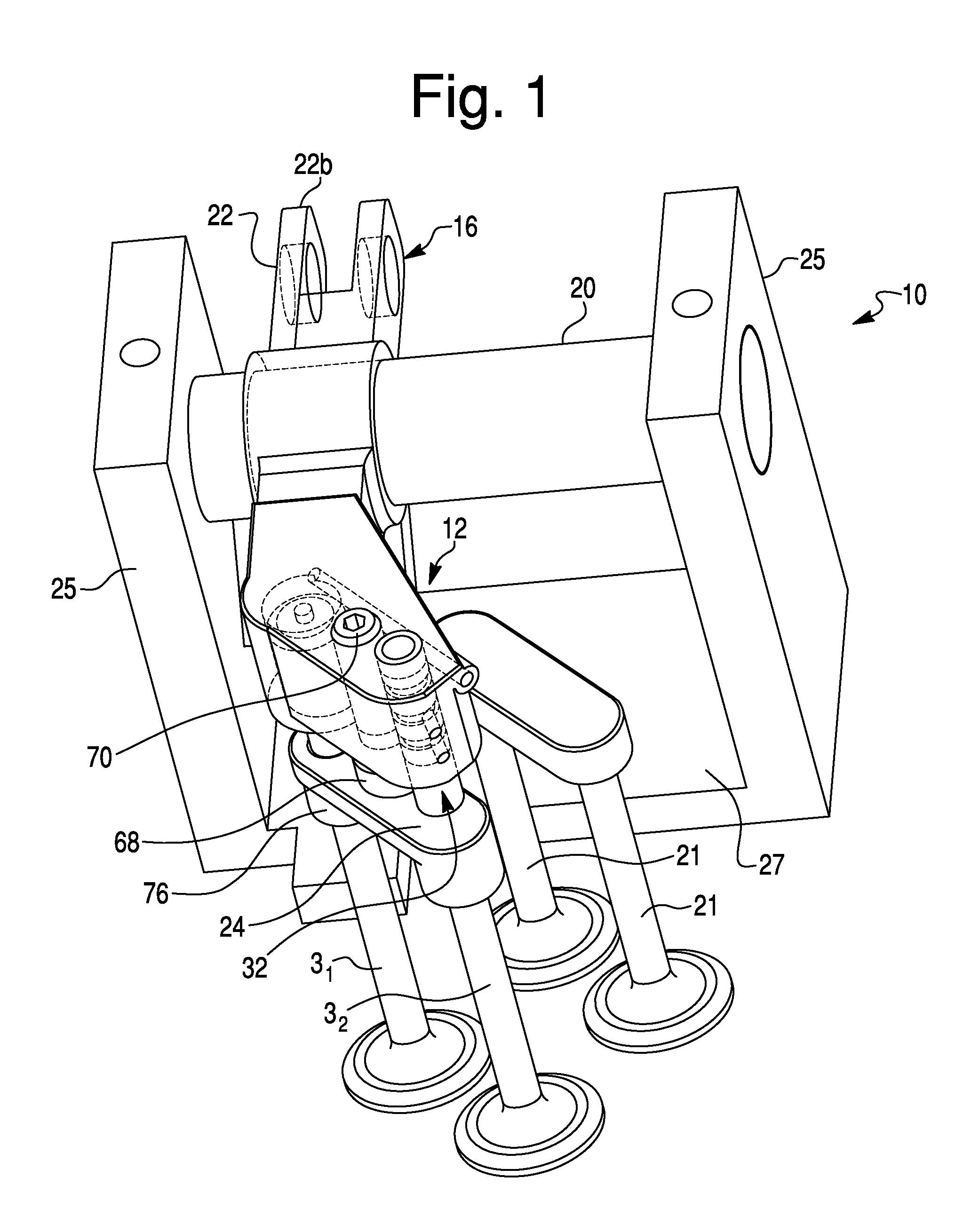
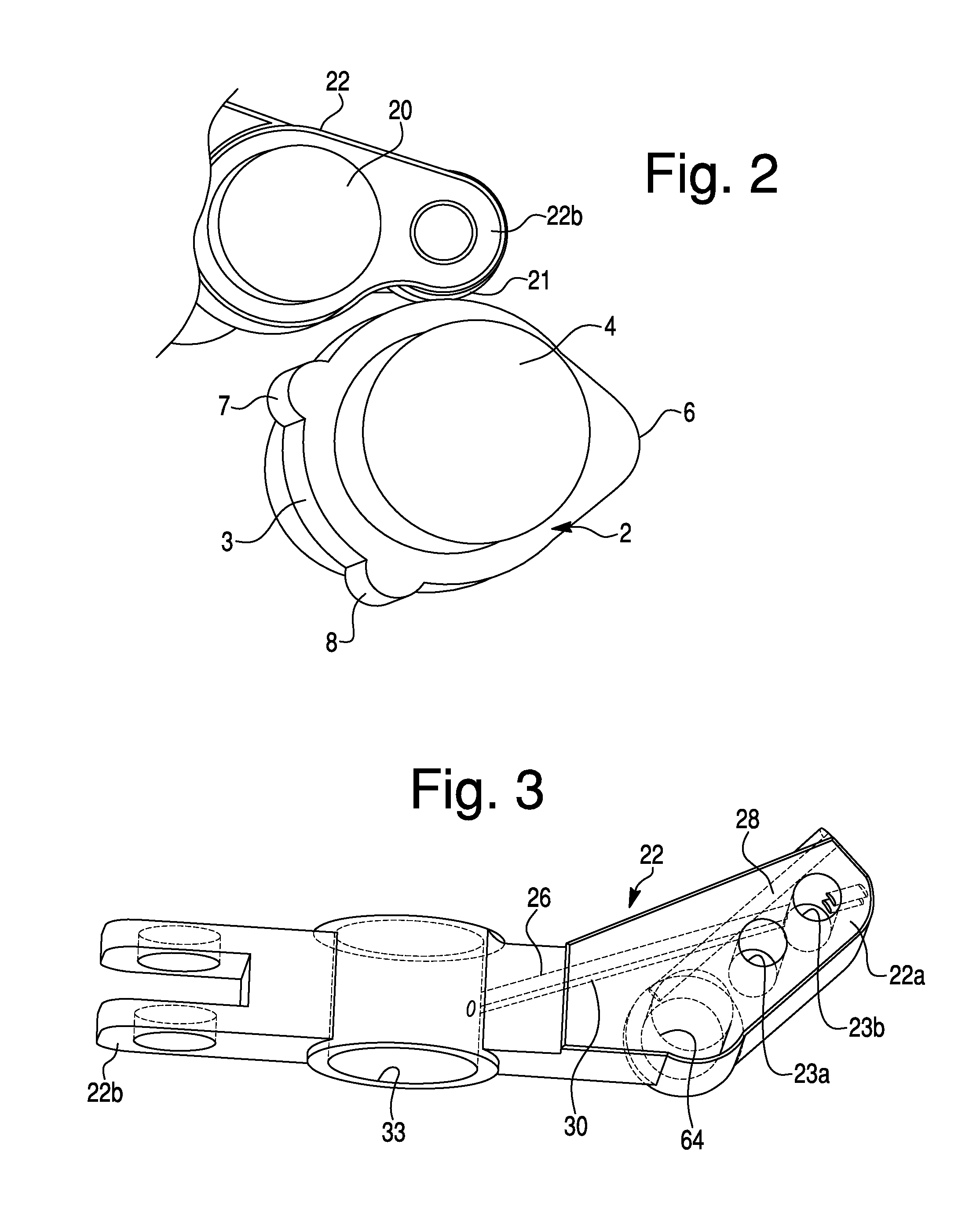
[0191]The compression-release brake system 512 is particularly useful for an IC engine, such as a four-stroke diesel engine, as generally shown in FIG. 36. The diesel engine comprises a cylinder block 11 and a plurality of cylinders 11′. Each engine cylinder 11′ is associated with at least one intake valve 1, at least one exhaust valve 31 / 32, at least one exhaust valve return spring 91 / 92 exerting a closing force on the exhaust valve 31 / 32 sufficient to urge the exhaust valve into a seated state, and an engine piston 13 configured to undergo reciprocating motion ...

fifth embodiment

[0234]The description of FIG. 12 in connection with the compression-release brake system 12 above is applicable to the compression-release brake system 512 of the The reset device 532 lowers or eliminates the exhaust / intake valve overlap 90 at TDC in brake-on mode. The accumulator for supplying “make-up” hydraulic fluid may be provided in the rocker arm shaft 20 and / or or the rocker arm supports 25. The compression-release brake system 512 opens one of two exhaust valves 31 during the engine compression release event and resets the exhaust valve 31 prior to the normal exhaust stroke valve motion, i.e., by the end of the expansion stroke. The engine compression release single exhaust valve lift opening may be approximately 0.100 inch with lift starting just prior to TDC of the compression stroke.

[0235]The compression-release engine brake system 512 of the fifth exemplary embodiment may provide various advantages, including reduced cost and enhanced performance compared to convention...

seventh embodiment

[0254]The positive power operation (brake-off mode) of the IC engine of the seventh exemplary embodiment is similar to the brake-off mode operation described above in connection with the fifth exemplary embodiment and FIGS. 24-26, with the following exception. In the dual-supply hydraulic circuit of the fifth exemplary embodiment, the supply conduit 526 and connecting conduits 528 and 529 are fed with hydraulic fluid in both the brake-off and brake-on modes, while the separate brake-on supply conduit 530 is fed with hydraulic fluid in the brake-on mode but not the brake-off mode. As discussed above, in both modes, the hydraulic fluid supplied through the supply conduit 526 fills the actuation piston cavity 565, moving the actuation piston 562 into its piston extended position and eliminating the valve train lash, except for the predetermined valve lash δ set between the foot 572 and the exhaust valve bridge 524, including between the cam follower 21 and the lobe of the exhaust cam 2...


PUM


Abstract

A compression-release brake system is provided that includes a lost motion exhaust rocker assembly, an actuation piston, and a reset device. The actuation piston includes an actuation piston body that is slidably received by the rocker arm to define a piston cavity in the rocker arm and is movable between piston retracted and extended positions. The actuation piston is configured to be operatively associated with the exhaust valve to permit unseating of the exhaust valve from the seated state. An actuation piston check valve is configured to move between closed and open positions to permit hydraulic fluid flow through an actuation piston communication port to the piston cavity. The reset device includes a reset check valve and a reset pressure control spring for applying a biasing force to the reset check valve to urge the reset check valve toward an open position.

Description

CROSS-REFERENCE TO RELATED APPLICATIONS AND CLAIM TO PRIORITY[0001]This application is a continuation-in-part of U.S. application Ser. No. 14 / 553,177, filed Nov. 25, 2014, which claims the benefit of U.S. Provisional Application No. 61 / 908,272 filed on Nov. 25, 2013 by V. Meneely and R. Price, and of U.S. Provisional Application No. 62 / 001,392 filed on May 21, 2014 by V. Meneely and R. Price, each of which are hereby incorporated herein by reference in their entireties and to which priority is claimed.BACKGROUND OF THE INVENTION[0002]1. Field of the Invention[0003]The present invention relates to compression-release engine brake systems in general, and more particularly to a compression-release engine brake system and method comprising a lost motion type engine brake rocker arm assembly incorporating structure implementing a valve reset function.[0004]2. Description of the Related Art[0005]Compression release engine brake systems (or retarders) for diesel engines were designed and d...

Claims


Application Information

Patent Timeline
Patent Type & Authority Applications(United States)
IPC IPC(8): F01L13/06F02B75/02F01L1/18
CPCF01L13/065F02B2075/027F02B75/02F01L1/18F01L1/08F01L1/146F01L1/181F01L1/20F01L1/26F01L13/06F01L2001/054F01L2013/105F01L2305/00F01L2820/01F02D13/04
Inventor MENEELY, VINCENTPRICE, ROBERT
Owner PACBRAKE
Why Eureka
Try Eureka