

Pulsed light generating method, pulse laser apparatus, exposure apparatus having pulse laser apparatus, and inspection apparatus having pulse laser apparatus
- Summary
- Abstract
- Description
- Claims
- Application Information
AI Technical Summary
Benefits of technology
Problems solved by technology
Method used
Image

Examples
Embodiment Construction
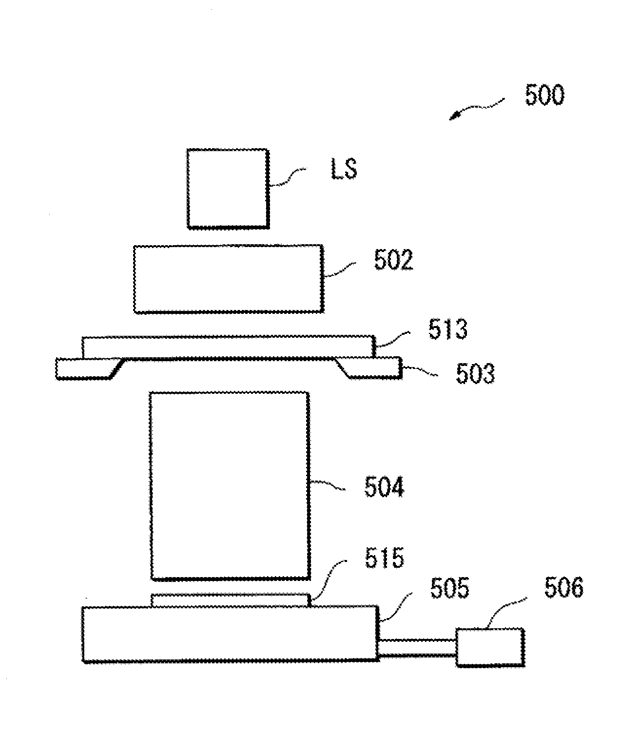
[0049]Embodiments of the present invention will now be described with reference to the drawings. FIG. 3 illustrates a schematic configuration diagram of a pulse laser apparatus LS, which is illustrated as one aspect of the present invention. The pulse laser apparatus LS is configured to include a laser light generation unit 1 that outputs a pulsed seed light, an amplification unit 2 that amplifies the seed light outputted from the laser light generation unit 1, an wavelength conversion unit 3 that converts a wavelength of the amplified light outputted from the amplification unit 2, and a control unit 8 that controls operation of the above-described units.
[0050]A variety of specific configuration forms of the laser light generation unit 1, the amplification unit 2, and the wavelength conversion unit 3 may be employed, as disclosed in the patent literatures mentioned above and other publications. This embodiment illustrates, as one example, a case where the seed light outputted from t...
PUM
 Abstract
Description
Claims
Application Information