Apparatus and method for solar panel on-board wiring

a solar panel and on-board wiring technology, applied in photovoltaic supports, climate sustainability, sustainable buildings, etc., can solve the problems of loose wiring being exposed to the elements and affecting the installation speed, and achieve the effect of reliable electrical connections and quick installation

Inactive Publication Date: 2016-12-08
LUMETA
View PDF7 Cites 36 Cited by
  • Summary
  • Abstract
  • Description
  • Claims
  • Application Information

AI Technical Summary

Benefits of technology

[0005]The photovoltaic module described herein and illustrated in the attached drawings enables electricity-generating solar modules to be installed quickly and with reliable electrical connections.

Problems solved by technology

A problem with above mentioned direct roof top attached crystalline silicon photovoltaic cell based solar modules is their installation tends to take a great deal of time in laying the panels out and then electrically connecting plural panels together to form the desired array.
An electrician is usually needed, and loose wiring often is left exposed to the elements.
However, these proposed solutions still require a skilled worker to run the different required wirings from module to module, or from groups of modules to groups of modules.

Method used


Image

  • Apparatus and method for solar panel on-board wiring
  • Apparatus and method for solar panel on-board wiring
  • Apparatus and method for solar panel on-board wiring

Examples


Embodiment Construction

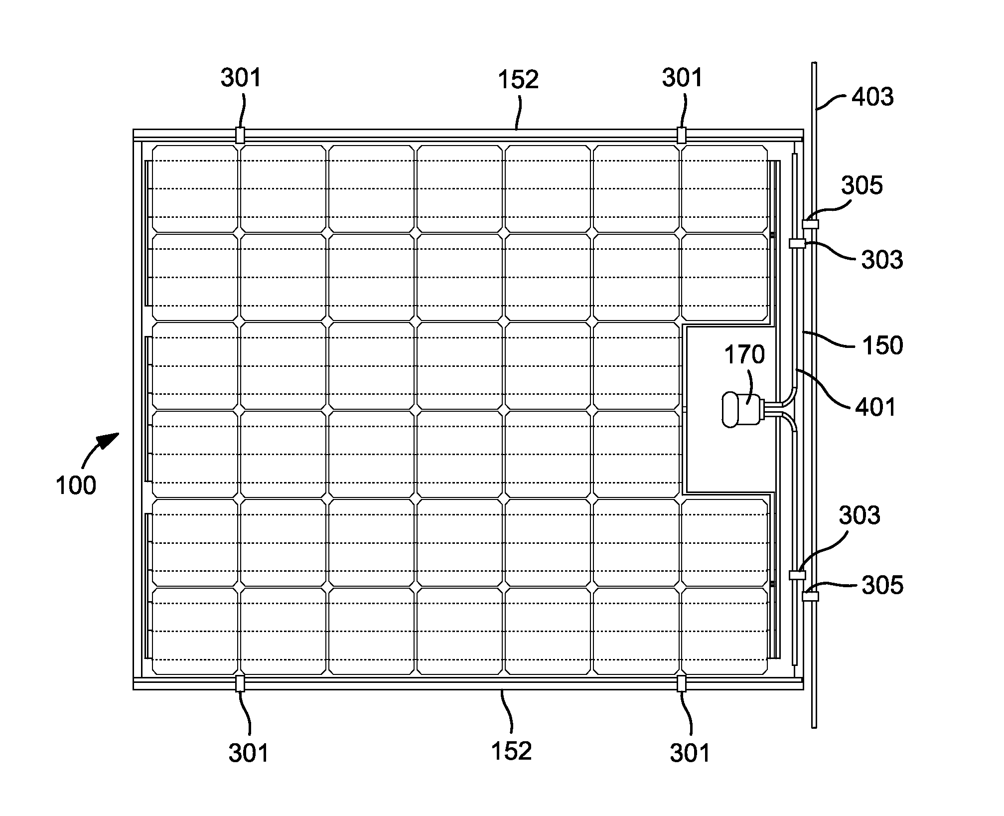
[0020]Briefly, the present on-board wire / cable management structures for both residential and commercial photovoltaic (“PV”) modules are designed to: (i) keep module interconnection wiring, jumpers, and homerun cables off roof surfaces, (ii) minimize system install time and wire tray usage, (iii) minimize installation errors in the field, and (iv) enhance protection from weather and solar related degradation. The low profile (height) of the wire clips does not substantially increase wind resistance of the installed photovoltaic systems and also enhances the aesthetics thereof. As wire management clips are exposed to direct sun light, stainless steel clips are preferred to minimize the impact of UV degradation. UV-resistant polymer materials can also be used for the wire clips.

[0021]PV wiring requirements for residential roof top installations should meet the National Electrical Code (“NEC”) latest revision, currently 2014. Many Authorities Having Jurisdiction (“AHJs”), such as state...


PUM


Abstract

A photovoltaic module generates electrical power when installed on a roof. The module is constructed as a laminated sandwich having a transparent protective upper layer adhered to a photovoltaic layer. The photovoltaic layer is adhered to the top of a rigid layer, preferably formed from a fiber reinforced plastic. A tapered edge seal is disposed about the peripheral outer edge of the module, so that water and debris easily run off. Preferably, the tapered edge seal is disposed adjacent the photovoltaic layer, and above the rigid substrate layer. The tapered edge seal is thinner at the outer peripheral portion thereof than at a portion thereof adjacent the photovoltaic layer. The laminated module preferably has a layer of double stick tape on the bottom to adhere the module to the surface of a roof.

Description

BACKGROUND OF THE INVENTION1. Field of the Invention[0001]The present invention relates to solar panels / modules for generating electrical energy, and more particularly to photovoltaic panels / modules with on-board wiring management structures.2. Description of the Related Art[0002]Conventional photovoltaic modules for generating electrical power for residences and businesses are often flat and are placed on a portion of a roof that is exposed to the sun. Historically, such modules were placed on structures erected on the roof to support and protect the modules. More recently, photovoltaic modules have become available that can be mounted directly on a flat or tilted roof. See, for example, US Patent Application Publication No. 2005 / 0178428 A1 to Laaly et al., (the entire contents of which are incorporated herein by reference), which discloses a module that incorporates a roofing membrane into the module structure. The module is intended to be installed on a new roof or replacement ro...

Claims


Application Information

Patent Timeline
Patent Type & Authority Applications(United States)
IPC IPC(8): H02S40/36H01L31/048
CPCH01L31/048H02S40/36H01L31/02013H02S20/23H02S30/10H02S40/34Y02B10/10Y02E10/50
Inventor MAO, ERWANGFLAHERTY, BRIAN JOSEPHDAVEY, TIMOTHY MICHAEL
Owner LUMETA
Why Eureka
Try Eureka