
Boiling-water geothermal heat exchanger and boiling-water geothermal power generation equipment

a geothermal heat exchanger and geothermal power generation technology, which is applied in indirect heat exchangers, machines/engines, lighting and heating apparatus, etc., can solve the problems of increasing the power of high-pressure pumps, reducing the output of power generation, and difficult prolonged use, so as to lighten the weight of piping

Inactive Publication Date: 2016-12-15
KYOEI ELECTRIC IND CORP
View PDF8 Cites 13 Cited by
  • Summary
  • Abstract
  • Description
  • Claims
  • Application Information

AI Technical Summary

Benefits of technology

The present invention is about a new type of geothermal system that can reduce heat transfer between high-temperature steam and water, making it more efficient. Additionally, the system is designed to make the piping lighter than previous versions.

Problems solved by technology

The adhesion of scale thereto decreases the output of power generation with the lapse of time, and makes prolonged use difficult.
First, a problem resides in the fact that the power of a high-pressure pump must be increased because of the pressure loss in piping of water fed under the ground and of hot water extracted by obtaining the supply of geothermal energy and in the fact that the diameter of a geothermal heat exchanger is required to be increased in order to raise generating efficiency while restricting the pump power to a low level.
Second, a problem resides in the fact that although the replacement of existing boreholes can be mentioned as one of the advantages brought about by Patent Document 1, boreholes to which replacement is applied are limited by limitations on the diameter of a geothermal heat exchanger.
The size of the diameter of a geothermal heat exchanger might be an obstacle even when the replacement etc., of boreholes for a geothermal energy survey and of boreholes being out of service are investigated, besides the replacement of existing boreholes.

Method used


Image

  • Boiling-water geothermal heat exchanger and boiling-water geothermal power generation equipment
  • Boiling-water geothermal heat exchanger and boiling-water geothermal power generation equipment
  • Boiling-water geothermal heat exchanger and boiling-water geothermal power generation equipment

Examples


first embodiment

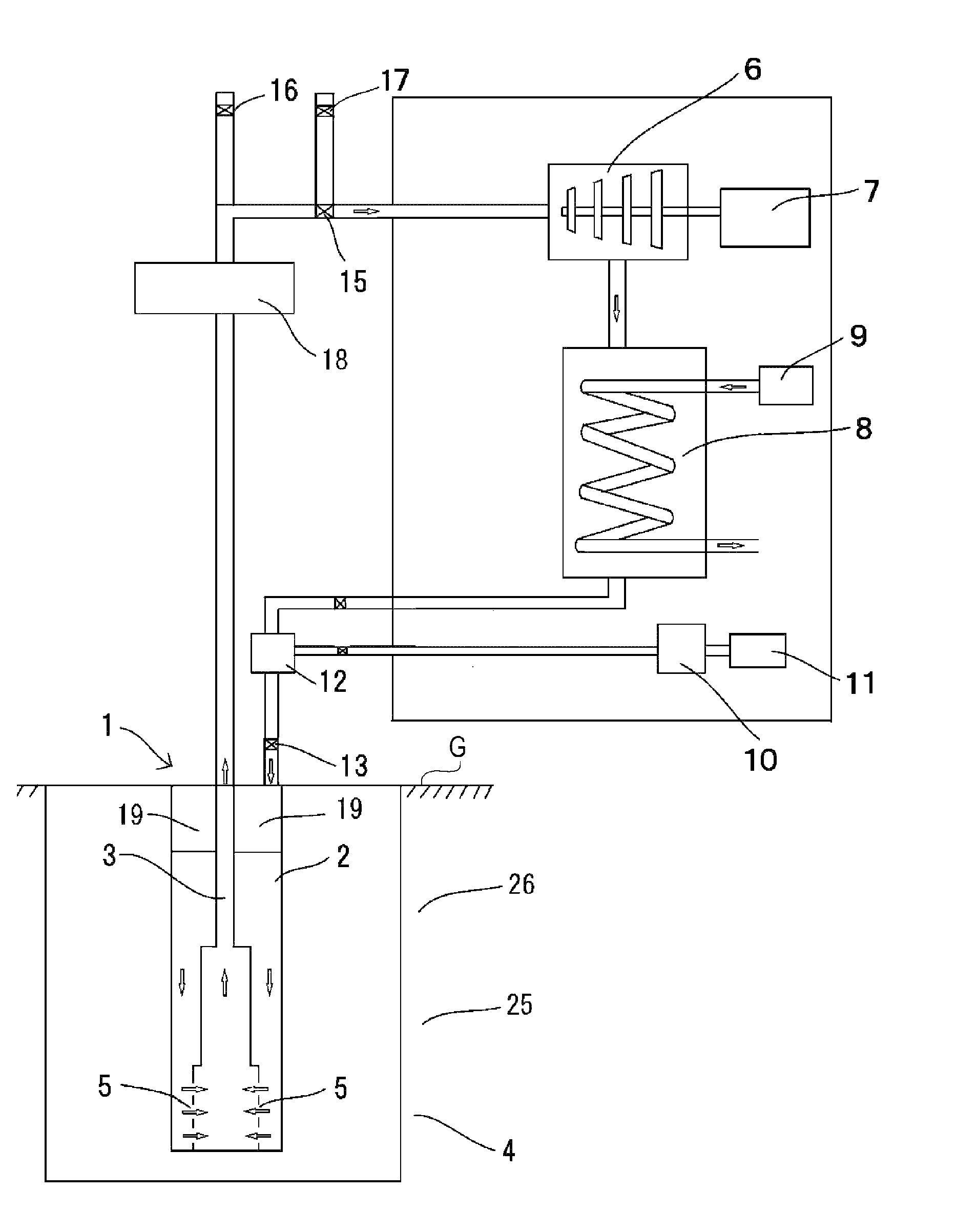
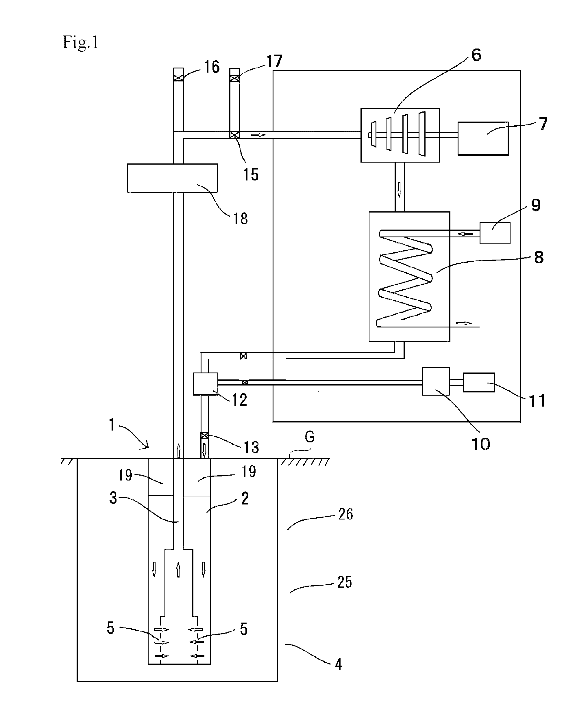
[0048]The steam extraction pipe 3 is formed such that the diameter of the steam extraction pipe 3 becomes smaller from the lower side of the geothermal region toward the upper side of the ground surface G. FIG. 1 shows a configuration that is its first embodiment in which the diameter of the steam extraction pipe 3 stepwisely becomes smaller from the lower side of the geothermal region toward the upper side of the ground surface G. The diameter of its part in the area of the intermediate-temperature region 25 is made smaller, and the diameter of its part in the area of the low-temperature region 26 is made even smaller than the diameter of its part in the geothermal region 4 that is a high-temperature region. That of FIG. 1 is one example, and the number of places at which the pipe diameter becomes smaller is not limited to the number shown here.

second embodiment

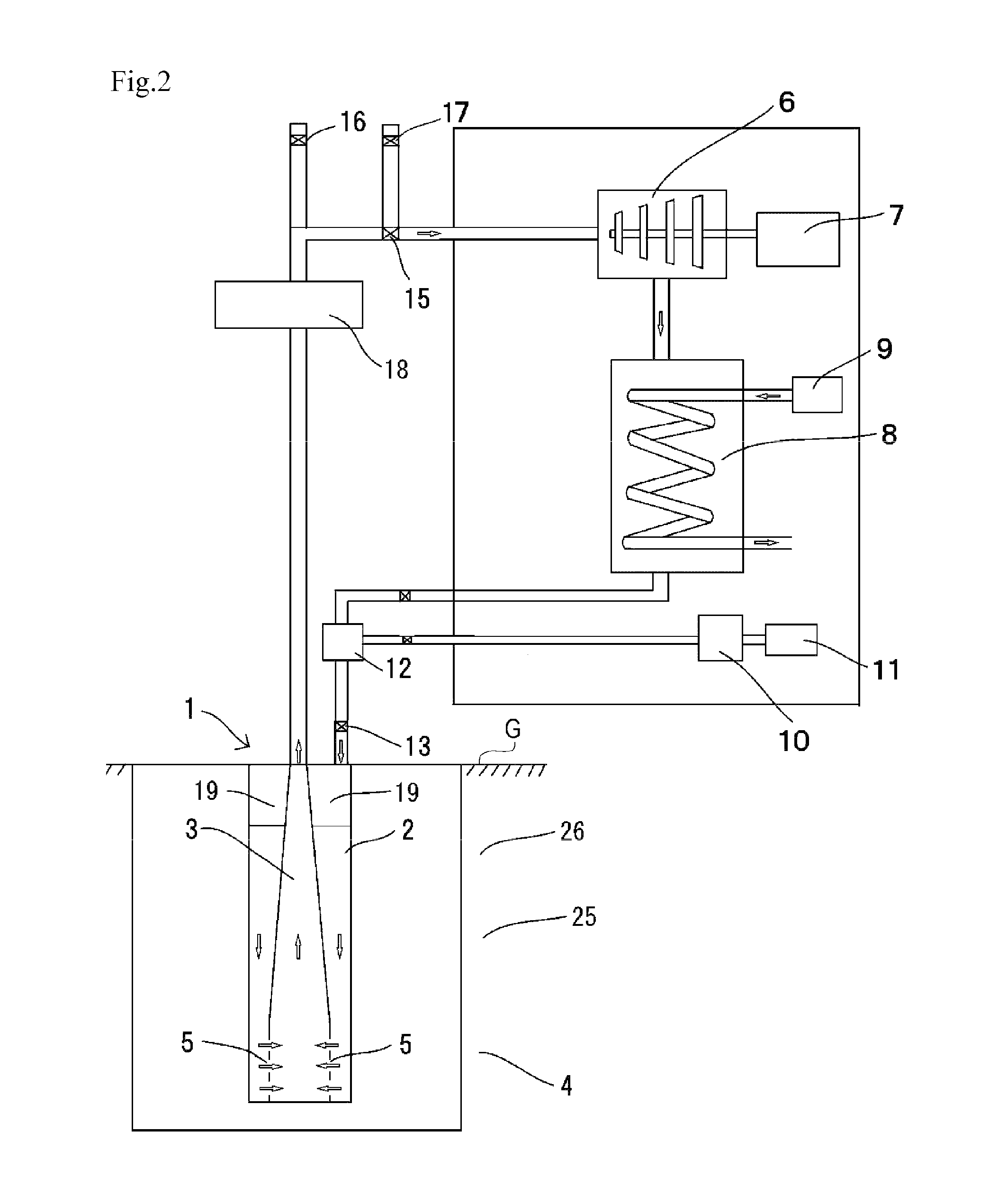
[0049]Additionally, FIG. 2 shows a configuration that is its second embodiment in which the diameter of the steam extraction pipe 3 continuously becomes smaller from the lower side of the geothermal region toward the upper side of the ground surface G. In FIG. 2, an example is illustrated in which the rate of a decrease in diameter is constant, and is linearly decreased with a predetermined inclination from the geothermal region 4 that is a high-temperature region to the low-temperature region 26 through the intermediate-temperature region 25, and yet the rate of a decrease in diameter is not necessarily required to be constant, and may be decreased in a curved manner. Additionally, a combination of a stepwise decrease in diameter and a continuous decrease in diameter may be employed.

[0050]The steam extraction pipe 3 is formed such that the diameter of the steam extraction pipe 3 becomes smaller from the lower side of the geothermal region toward the upper side of the ground surface...


PUM


Abstract

A geothermal heat exchanger 1 includes a water injection pipe 2 that is installed underground and to which water is supplied from above ground and a steam extraction pipe 3 that is installed underground so as to be contiguous to the water injection pipe 2. The steam extraction pipe 3 has a plurality of gushing ports 5 at its lower part, and pressure in the steam extraction pipe 3 is decreased approximately to pressure required by a turbine 6. The steam extraction pipe 3 is formed such that the diameter of the steam extraction pipe 3 becomes smaller from the lower side of the geothermal region toward the upper side of a ground surface G. Water supplied to the water injection pipe 2 becomes high-temperature pressurized water by heat supplied from the geothermal region 4, and gushes from the gushing ports 5 into the steam extraction pipe 3 in an atomized state, and is then converted into a steam single-phase flow, and allows a power generator 7 to conduct power generation. Furthermore, an air layer 19 is formed at the upper part of the water injection pipe 2 by lowering the water level of water that is supplied to the water injection pipe 2, and a heat insulating portion defined thereby is provided in a region contiguous to a low-temperature region 26 closer to the ground surface.

Description

BACKGROUND OF THE INVENTION[0001]Technical Field[0002]The present invention relates to a boiling-water-type geothermal heat exchanger and boiling-water-type geothermal power generation equipment that are capable of efficiently extracting geothermal energy.[0003]Background Art[0004]Geothermal power generation to generate electric power while utilizing geothermal energy uses a high-temperature magma layer as a heat source, and is able to utilize its energy as semi-permanent thermal energy, and does not produce a greenhouse gas in the process of power generation, and hence has attracted attention as an alternative means to fossil fuel in recent years.[0005]In conventional geothermal power generation, boring is conducted at a geothermal region, and electric power is generated by extracting natural steam and hot water present in the geothermal region while utilizing natural pressure. Therefore, the thus extracted steam and hot water contain a large amount of sulfur and other impurities u...

Claims


Application Information

Patent Timeline
Patent Type & Authority Applications(United States)
IPC IPC(8): F24J3/08F01K7/16F03G7/04
CPCF24J3/084F01K7/16F03G7/04F01K25/10F01K27/02F24T10/17Y02E10/10F28D7/12
Inventor TAHARA, SHUNICHI
Owner KYOEI ELECTRIC IND CORP
Learn More